Contact: sales@haomai.net
NEWS
Company News
Polarity Verification Test for High-voltage and Low-voltage Sides of Station Transformer
01 Test Wiring

At the 220kV WB-W15 bay, open the earthing switch Q21 and close the earthing switch Q22. High-current Source 1 injects a large current from the P1 terminal of the CT; the current flows through the CT (from P1 to P2) and into the ground to form a loop.
On the 202B 10kV line, High-current Source 2 injects a large current from both sides of the CT (from P1 to P2).
Considering the long distance and various obstacles in between, one wireless repeater is placed near each of High-current Source 1 and High-current Source 2 respectively. Operate the YD-300 Wireless Telemetry Voltmeter-Ammeter Phase Indicator in the 220kV protection room, and connect the secondary side voltage of the running PT to the YD-300 as the reference phase of the benchmark voltage.
Use the YD-300 to remotely control High-current Source 1 and High-current Source 2 to output currents synchronously. Check whether the current amplitude and phase of the high-voltage side and low-voltage side on the protection device are consistent with the set values. If consistent, inject currents with opposite phases into the high-voltage side and low-voltage side, check whether the differential current is correct, and judge the polarity accordingly.
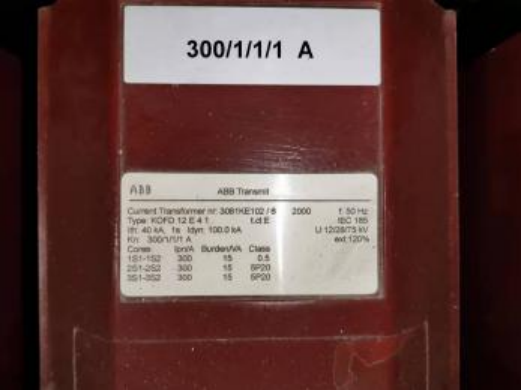
The CT ratio of 220kV side is 2500:1; the CT ratio of 10kV side is 300:1.
02 Required Equipment
- 1 unit of HTA-3100 Three-phase Digital Intelligent High-current Source and 1 unit of HTA-3300 Three-phase Digital Intelligent High-current Source
- 1 unit of YD-300 Wireless Telemetry Voltmeter-Ammeter Phase Indicator
- 2 units of Intelligent Wireless Telemetry Repeaters

The current direction of the transformer high-voltage side is into the transformer, and the current direction of the low-voltage side is out of the transformer. To adapt to the wiring polarity of the current loop, the current phase of the high-voltage side of the test device is set to 0°, 240°, 120°, and the current phase of the low-voltage side is set to 180° added to each phase, i.e., 180°, 60°, 300°.
03 Test Settings
Benchmark Reference Voltage: UA = 57.7V, phase = 0°
CT Ratio of High-voltage Side: 2500:1; CT Ratio of Low-voltage Side: 300:1
|
Phase |
Set Current Amplitude (A) |
Set Current Phase (°) |
Secondary Current Amplitude on Protection Device (A) |
Secondary Current Phase on Protection Device (°) |
|
Iha |
50 |
0 |
0.02 |
0 |
|
Ihb |
50 |
240 |
0.02 |
-120 |
|
Ihc |
50 |
120 |
0.02 |
120 |
|
Ila |
30 |
180 |
0.1 |
180 |
|
Ilb |
30 |
60 |
0.1 |
60 |
|
Ilc |
30 |
300 |
0.1 |
300 |
|
|
|
|
|
|
04 Test Method
First, conduct a local test and inject current with a single device on one side to judge whether the output is normal.
The CT ratio of the 220kV side is 2500:1. Injecting 50A current from the primary side, the secondary protection device displays 20mA; the CT ratio of the 10kV side is 300:1. Injecting 30A current from the primary side, the secondary protection device displays 100mA.
First, inject current in manual mode on the high-voltage side with a value of 50A.

At this time, use a clamp meter to measure the secondary current amplitude of the high-voltage side on the secondary side. It can be seen that the output and ratio of the high-voltage side are normal, and then inject current in manual mode on the low-voltage side.

Use a clamp meter to measure that the secondary current amplitude of the low-voltage side on the secondary side is 100mA, indicating that the output of both the high-voltage and low-voltage sides of the device is normal.
Use the remote control mode to control the high-current sources on the high-voltage and low-voltage sides to output currents simultaneously for phase synchronization. First, output 0°, 240°, 120° for both the high-voltage and low-voltage sides, i.e., the same polarity for the high-voltage and low-voltage sides of the transformer. It can be seen from the recording file that the amplitude output is normal and the phases are the same.

Then simulate the normal operation state of the transformer for current injection, i.e., the polarity of the 220kV side is opposite to that of the 10kV side. The high-voltage side is injected with 0°, 240°, 120°, and the polarity of the low-voltage side is reversed by 180°, i.e., 180°, 60°, 300°.


Read from the recording device that the primary current amplitude of the station transformer at this time is about 45A.
05 Test Results

The CT ratio of the 220kV side is 2500:1, the CT ratio of the 10kV side is 300:1, and the capacity of this transformer is 15MVA.
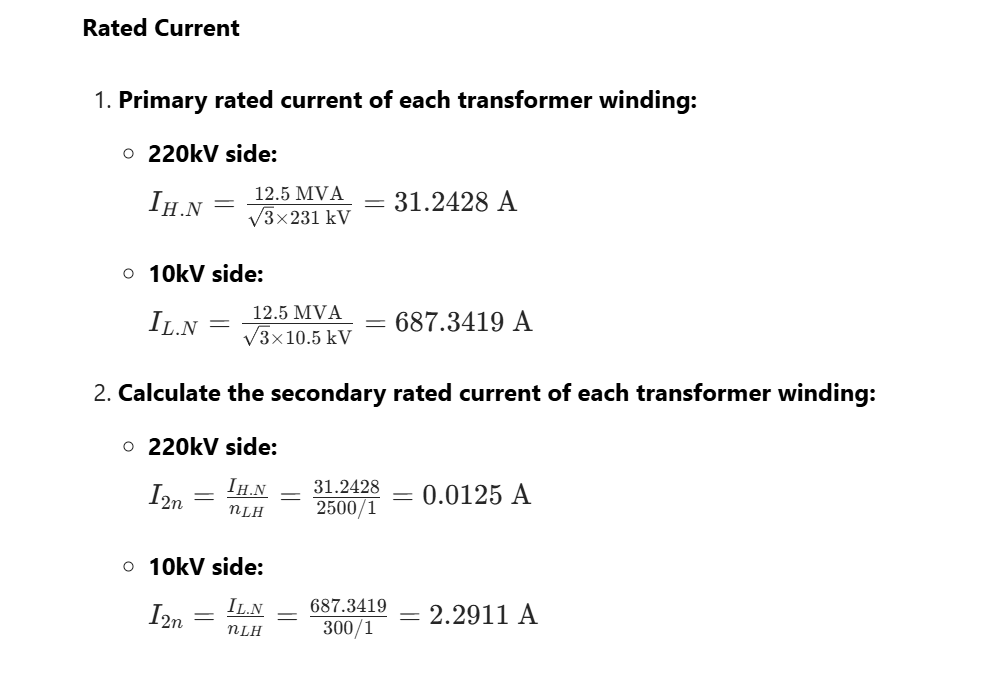
The actual current of the high-voltage side is 45A, and that of the low-voltage side is 30A. The calculation shows that the high-voltage side current is 1.44Ie, and the low-voltage side current is 0.044Ie. The differential current value read from the recording device is about 1.4Ie, which is consistent with the differential current value calculated by the formula when the polarities of the high-voltage and low-voltage sides are opposite under this current condition. Therefore, the polarity is correct.
24-hours hot line 400-099-8859 technical hot line: 13971234137

Copyright © 2024 All rights Reserved.
备案号:鄂ICP备05010718号-1
