Contact: sales@haomai.net
NEWS
Company News
Principle and Method for Capacity Verification of Substation DC System
The DC system of a 110kV substation consists of 24 units of 12V200AH batteries and 24 intelligent modules connected in parallel to form a DC power supply system. Its busbar and battery modules are divided into two sections, with 12 batteries in each section.
The parallel DC power supply system is composed of the parallel connection of high-voltage output terminals of several parallel battery modules. Each module can be equipped with 12V storage batteries to provide high-voltage DC220V/110V. The system is configured with several DC feeder branches, an insulation monitoring device, a switch quantity monitoring device, a system monitoring touch screen device, etc.

△ FDT-220/110 DC System Comprehensive Tester
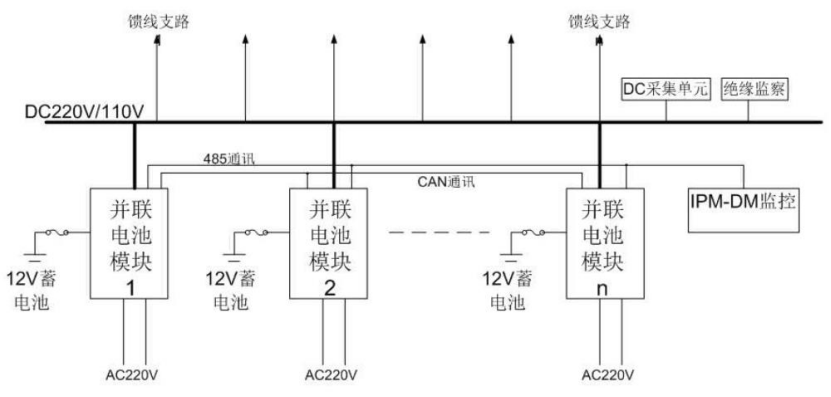
△ System Schematic Diagram
Principle of Capacity Verification for Parallel DC Power Supply System
When the AC input of the DC power supply system is normal, set the depth (capacity) and interval cycle of capacity verification on the system monitoring interface. When the capacity verification conditions are met, the system monitoring screen automatically issues a capacity verification command to the module to perform capacity verification on the storage battery matched with the module. After receiving the command, the module exits the system current sharing mode, internally shuts down the AC/DC converter, switches the battery management from charging mode to discharging mode, and dynamically fine-tunes the output voltage to realize constant-current discharging of the storage battery. As the battery voltage changes, the output terminal is dynamically adjusted until the battery terminal voltage reaches the cut-off voltage of 10.8V. Then the AC/DC converter is turned on to realize AC-powered loading, and the charging converter is activated at the same time to charge the storage battery, thus completing the online capacity verification process of the battery to be verified. During the entire capacity verification and discharging process, the monitoring system records the battery voltage and current every half an hour until the equalizing charging is completed, and allocates storage space inside the monitoring system for data saving. The corresponding capacity verification data can be exported on the data export page. When one module in the system is undergoing capacity verification, other modules are in AC-powered loading mode and perform charging management on their respective configured storage batteries. The system monitoring can also manually issue commands to start capacity verification for a single storage battery.

△ Capacity Verification Regulation Flow Chart
Conditions for Automatic Online Capacity Verification of Parallel DC Power Supply System
The automatic online capacity verification of the parallel DC power supply system can be implemented only when the following conditions are met simultaneously:
- The AC system is in normal state;
- The storage batteries are in floating charge stage;
- The load of the DC system can meet the minimum load required for capacity verification.
Operation Steps for Capacity Verification of a Single Battery
Main Monitoring Screen → DC Power Supply → Corresponding Capacity Verification Module → Module Parameter Settings → Enter Password → Click Capacity Verification.
Notes
- Capacity verification is not allowed when the module is in equalizing charge state;
- Check the module status on the module LCD screen;

- To exit capacity verification, click Stop Capacity Verification; the module will automatically switch to equalizing charge mode after exiting.
Simultaneous Capacity Verification Operation for Multiple Batteries
- Check the system current load I1, determine the external load I2 and the battery capacity C0.

- Calculate the number of modules required for normal simultaneous operation N1=I1×220/12/0.1C0, and the number of batteries that can undergo capacity verification simultaneously n=N0−N1.Take one section of the 110kV substation as an example: N0 is the total number of modules; the number of modules required to ensure normal system operation N1=7.8×220/12/20=7.15; that is, 8 modules must operate normally to ensure the normal operation of the system. The number of batteries that can undergo capacity verification simultaneously in this section of the battery pack is n=N0−N1=12−8=4.
- Connect the batteries to be verified simultaneously to the wireless single-battery monitoring system. Connect the black wire of the module to the negative poles of two batteries, and the red wire to the negative pole of the battery. When the communication indicator flashes red, the module is operating normally. The real-time voltage data of the single storage battery is transmitted to the FDT-220/110 DC System Comprehensive Tester through the wireless single-battery monitoring system, which directly reflects the real-time changes of battery voltage. This avoids continuous voltage measurement with a multimeter and greatly reduces the workload.

- Locate the discharge switch K of the DC power supply system or the standby switch Z of the feeder panel branch. (The rated current I of K or Z shall meet I>12×0.1C0×n/220) Verify the positive and negative poles, and connect the FDT-220/110 DC System Comprehensive Tester to the busbar system.

- After the connection is completed, enter the parameter setting interface. Set the number of wireless modules according to the number of batteries n to be verified, the nominal voltage U of the single battery, the lower limit voltage U0 of the single battery, the lower limit voltage of the battery section U1=N×n, and the half-capacity verification time to 300 minutes. After the settings are completed, start the battery capacity verification. The FDT-220/110 DC System Comprehensive Tester operates automatically and generates data files and data reports. When the voltage UE of a single battery drops to the lower limit voltage U0, the tester will automatically record the data and trigger an alarm.
- Wait for the completion of capacity verification of n batteries. Click to close the battery capacity verification dialog box on the DC monitoring system interface, and the system will automatically perform equalizing charging on the verified batteries. Then select the unverified batteries and repeat the above steps to complete the capacity verification of the DC power supply system.
24-hours hot line 400-099-8859 technical hot line: 13971234137

Copyright © 2024 All rights Reserved.
备案号:鄂ICP备05010718号-1
