Contact: sales@haomai.net
NEWS
Company News
Case Practice | Test Method for Line Inverse Time Overcurrent Protection
Test Device: CSC-211 Line Protection and Measurement & Control Device
Test Instrument: Relaystar-Z70 Handheld Digital-analog Integrated Relay Protection Tester

△ Relaystar-Z70 Handheld Digital-analog Integrated Relay Protection Tester
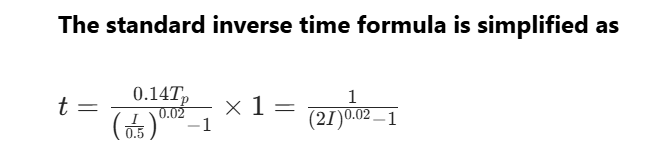
The inverse time overcurrent protection element is a protection component whose operating time limit is naturally coordinated with the magnitude of the current in the protected line. By horizontally shifting the operating curve, full-line coordination can be easily achieved. The operating time limit of inverse time overcurrent protection is related to the magnitude of the fault current in the protected line—the larger the fault current, the shorter the operating time limit; conversely, the smaller the fault current, the longer the operating time limit. The IEC inverse time characteristic analytical formulas are divided into three types, namely standard inverse time, very inverse time and extremely inverse time. The formulas for various inverse time characteristics are as follows:

The following describes the commissioning of inverse time overcurrent protection using the Relaystar-Z70 Handheld Digital-analog Integrated Relay Protection Tester.
1 Protection-related Settings
- Protection Setting Value and Control Word Configuration
|
Serial Number |
Setting Name |
Value |
Serial Number |
Setting Name |
Value |
|
01 |
Current Inverse Time Base Value |
0.5A |
04 |
Zero-sequence Inverse Time Base Value |
2A |
|
02 |
Current Inverse Time Setting |
1s |
05 |
Zero-sequence Inverse Time Setting |
1s |
|
03 |
Inverse Time Exponent |
0.02 |
06 |
Current Inverse Time Protection Enable |
1 |
- Protection Press Plate Configuration
Click "Operation Settings" — "Press Plate Settings", set the "Current Stage III" soft press plate to "1", and set all other press plates to "0".
The device is equipped with definite time and inverse time overcurrent protection functions for phase-to-phase current and zero-sequence current. The inverse time mode is selected through the above control word settings. At this time, the device automatically exits the definite time stage II and III overcurrent protection as well as stage II and III zero-sequence current protection elements. The function press plates for phase-to-phase current stage III and zero-sequence current stage III are automatically switched to the phase-to-phase current inverse time protection and zero-sequence current inverse time protection enable/disable press plates respectively.
The inverse time exponent is set to 0.02, indicating that the general inverse time formula is adopted, where the current inverse time base value Ip=0.05A, and the current inverse time setting 0.14Tp=1s.
Note: The zero-sequence inverse time overcurrent protection test can refer to the current inverse time overcurrent protection test method.
2 Test Wiring
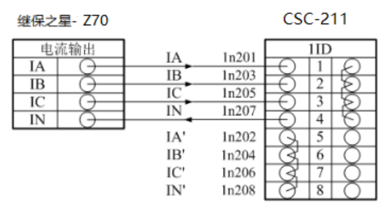
△ Inverse Time Overcurrent Protection Wiring Diagram
Connect the current output terminals "Ia", "Ib", "Ic" of the Relaystar-Z70 to the AC current terminals "IA", "IB", "IC" (polarity terminals) of the protection device respectively. Then short-circuit the AC current terminals "IA'", "IB'", "IC'", "IN'" (non-polarity terminals) of the protection device, and connect the "IN" (zero-sequence current polarity terminal) back to the current output terminal "In" of the tester. Connect the input contact "A" of the tester to the phase-separated trip output contact "Trip A" of the protection device, and connect the "+KM" terminal of the tester to the common terminal of the protection device.
3 Inverse Time Overcurrent Protection Verification
The main software interface of the Relaystar-Z70 includes various common test modules. Click "Switch to Digital Mode" to switch between analog quantity mode and digital quantity mode.

△ Software Main Interface
Relationship Table Between Input Current and Theoretical Operating Time
|
Input Current I (Reference) |
Operating Time t |
|
6A |
19.607s |
|
5A |
21.218s |
|
4A |
23.548s |
|
3A |
27.408s |
|
2A |
35.569s |
|
1.5A |
45.014s |
During the actual quantity injection test, set the above currents in the AC test module respectively and click "Run". The actual operating conditions corresponding to each current are shown in the figure below.

△ Inverse Time Overcurrent Protection Operation Message
4 Inverse Time Overcurrent Protection Operating Curve
Based on the test results, plot the operating curve of the inverse time overcurrent protection as follows:
△ Inverse Time Overcurrent Protection Operating Curve
24-hours hot line 400-099-8859 technical hot line: 13971234137

Copyright © 2024 All rights Reserved.
备案号:鄂ICP备05010718号-1
