Contact: sales@haomai.net
NEWS
Company News
Case Practice | Load Simulation-based Relay Protection Vector Check for 800kV Converter Station
1. Test Mode
The test mode adopted this time is three-phase current and voltage injection on the valve side, with the grid side short-circuited and grounded. The current injection bays cover the Y/Y and Y/D phase-splitting converter transformers in Pole 1 Low Valve Hall and Pole 2 Low Valve Hall. The current injection device used is the HTB-8000 Large Transformer Primary Current Injection Test Device.
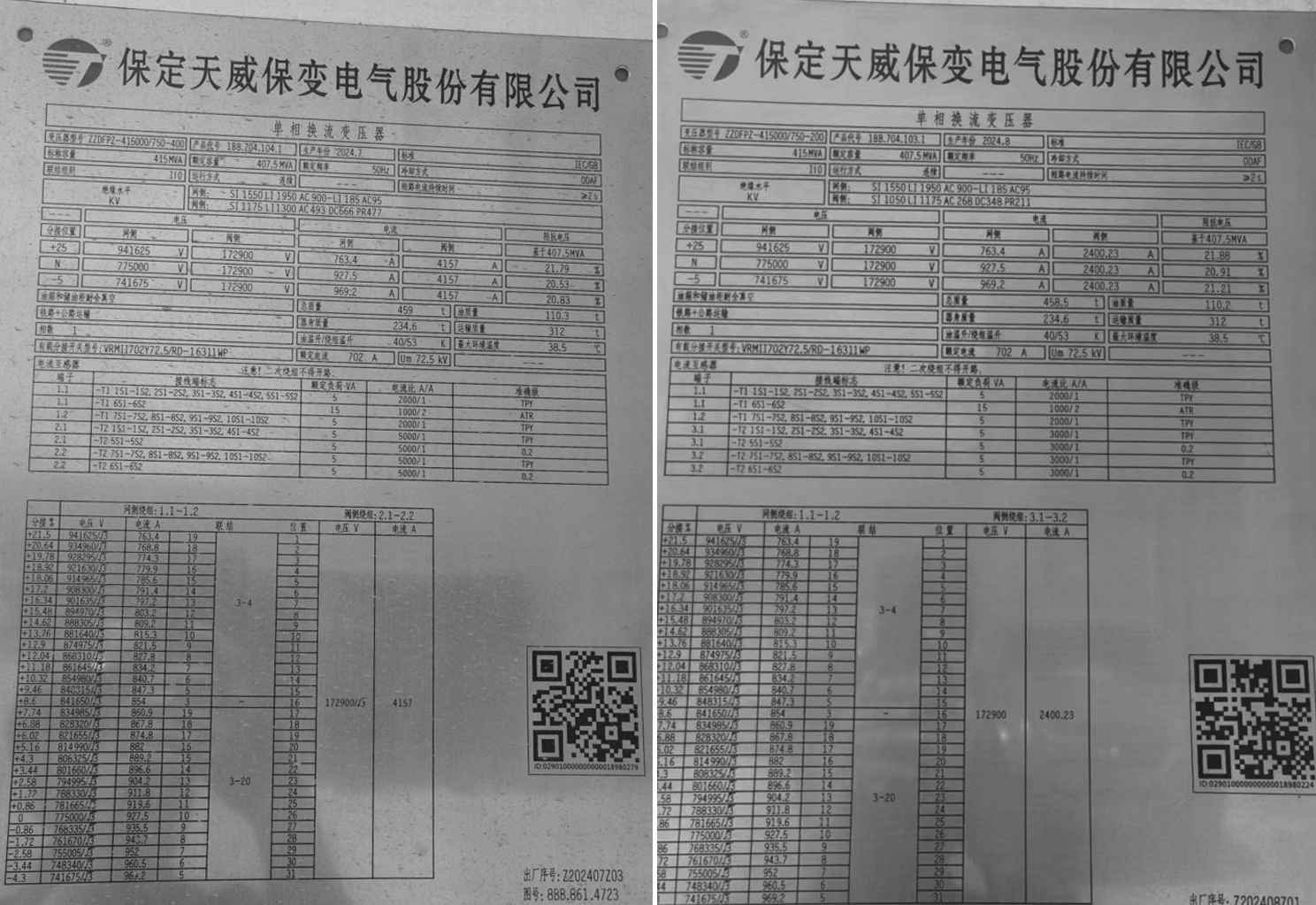
Analysis of Transformer Nameplate Parameters:
In the mode of current injection on the grid side with the valve side short-circuited and grounded, the grid-side current is too small to achieve the test objectives. Therefore, the test uses current injection on the valve side with the grid side short-circuited and grounded.
Between the Y/D and Y/Y connection modes:
- The rated voltage level of the valve side in Y/Y mode is √3 times higher than that in Y/D mode. As a result, the impedance of the Y/Y mode (5Ω) is lower than the minimum required compensation impedance (6.5Ω), so a series reactor must be connected to increase the loop impedance.
- For the Y/D mode, since there is no √3 factor on the valve side but a √3 factor exists on the grid side, calculating the induced current using the current ratio yields a more accurate primary current value compared with the calculation based on the voltage ratio.
2. Current Injection Test
1) Pre-test Preparation
- Power Supply for the Device

△ Power Extraction at the Maintenance Box Power Supply
- Application of Reference Voltage

△ Power Supply Box Near the PT Terminal Box △ Three-phase Voltage Extraction from the Power Supply Box

△ PT Terminal Box △ Secondary Reference Voltage Injection into the PT Terminal Box △ Reference Voltage Box
As shown in the figures above:The HTB-8000 Large Transformer Primary Current Injection Test Device takes the phase A voltage from the power extraction point (the substation maintenance box power supply) as the reference. Since the opposite side (grid side), which is short-circuited and grounded, has no primary voltage but only primary current, it is necessary to output a secondary homologous reference voltage (with the phase A voltage of the maintenance box power supply as the reference) to the secondary side of the protection device on the opposite side (grid side).
2) Current Injection for Y/Y Mode in Pole 1 Low Valve Hall
A primary current of 100A is applied to the valve side, and an induced primary current of 22A is generated on the grid side. The transformation ratio of the valve side is 5000/1, and that of the grid side is 2500/1. A series reactor must be connected in the circuit to increase the loop impedance.

△ Reactor Parameters
As shown in the figure above:The inductance of the reactor is 5mH. According to the formula Z=2πfL, the impedance of the reactor at power frequency is 1.57Ω, with a fixed phase shift of 90°. The loop impedance between the valve side and grid side in Y/Y mode is 5.02Ω; adding the reactor impedance results in a total loop impedance of 6.59Ω, which meets the minimum impedance requirement for device compensation.

The HTB-8000 outputs a primary voltage of 660V and a primary current of 100A, with a loop impedance of approximately 6.6Ω—consistent with the pre-test calculation value.
3) Current Injection for Y/D Mode in Pole 1 Low Valve Hall
A primary current of 80A is applied to the valve side, and an induced primary current of 30.9A is generated on the grid side. The transformation ratio of the valve side is 5000/1, and that of the grid side is 2500/1.

△ Current Injection by HTB-8000
- Differences Between Y/Y and Y/D Modes at the Current Injection Point

△ Valve Side Current Injection in Y/Y Mode
For Y/Y mode valve side current injection:Simply clamp the A, B, C phase clips of the device to the corresponding three phases on the converter transformer valve side, clamp the N line clip to the ground bar, and short-circuit and ground the grid side.

△ Valve Side Current Injection in Y/D Mode
Differences between Y/Y and Y/D mode valve side current injection:
The valve side of Y/Y mode uses a star connection; the valve side of Y/D mode uses a delta connection (the head end of phase C is connected to the tail end of phase A, the tail end of phase C is connected to the head end of phase B, and the tail end of phase B is connected to the head end of phase A).
If the device's three phases are directly clamped to the A, B, C phases of the converter transformer valve side in Y/D mode, the loop impedance will deviate from the calculated value. Therefore, it is necessary to disconnect the leads between B and Cn, and between A and Bn, and convert the valve hall delta connection to a star connection.
Clamp the device's A, B, C phases to the corresponding three phases on the valve side, and clamp the N line clip to the neutral point (N) of each phase of the converter transformer. This is equivalent to applying single-phase current injection and voltage application three times, so there is no need to consider the three-phase balance of the device.
The current injection method for Pole 2 Low Valve Hall is the same as that for Pole 1 Low Valve Hall, and the above method can be referred to.
24-hours hot line 400-099-8859 technical hot line: 13971234137

Copyright © 2024 All rights Reserved.
备案号:鄂ICP备05010718号-1
