Contact: sales@haomai.net
NEWS
Company News
Load Simulation-based Relay Protection Vector Check | Test Method for Homologous Voltage and Current Application
1. Principle of Homologous Current Injection Test
The HTB-8000 Large Transformer Primary Current Injection Test Device adopts a new method of series and parallel capacitor compensation: it applies voltage and current to transformer windings, and uses the short-circuit impedance of large transformers to conduct current injection tests. In the primary current injection circuit of large transformers, series capacitors are used to compensate part of the inductive reactance and reduce the test circuit impedance; then parallel compensation capacitors are used to reduce the test power supply current, thus completing the primary current injection test for large power transformers.
The device can select different voltage application/current injection points and transformer short-circuit contacts in the primary system circuit of newly-built, expanded, or renovated substations or converter stations. The current injection can be extended to the busbars and line bays connected to each winding of the transformer. Each phase's injected current has a fixed phase relationship with the test power supply. By matching the voltage input from the secondary circuit of the voltage transformer to the test device, the simulated load and vector verification tests of control and protection devices can be completed.

2. Features of Homologous Current Injection Test
The homologous method uses a relatively small voltage from the power supply side to output a large voltage, and forms the circuit current through the short-circuit impedance of the transformer. Therefore, it can verify the main transformer bushing CT and has low requirements for the power supply.
Since the transformer can be regarded as a purely inductive load, the current lags behind the voltage by nearly 90° when alternating current passes through an inductive load. When the device sets the phase A of the output voltage to 0°, the phase A current lags behind the phase A voltage by nearly 90°—this fixed phase relationship between current and voltage is used to verify the CT polarity.
Compared with the non-homologous method, the homologous method provides both current and voltage on the busbar, simulating the real load-carrying phenomenon of the busbar. The device takes power from the station transformer, and applies voltage with the phase A of the station transformer as 0°, ensuring the same phase as the station transformer power supply. When the opposite side is three-phase short-circuited and grounded, only current remains on the busbar: by taking the 220V phase A of the maintenance box power supply (station transformer power supply) through the reference voltage box, and outputting 57V secondary voltage to the protection side, the reference voltage of the opposite side can be made to have the same power supply and phase as the device.
3. Angle Analysis of the Secondary Circuit in Homologous Current Injection Test
The phase A current lags behind the phase A voltage by nearly 90°, so in the primary circuit, the I-U angle is 270° positive sequence.
- Current Injection from Medium-Voltage Side (110kV) to High-Voltage Side (220kV)
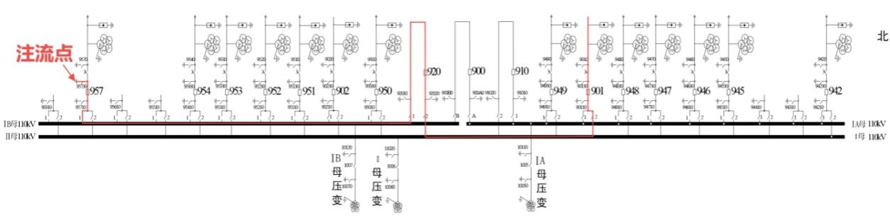
△ Medium-Voltage Side
In the figure above, the current injection point is the line bay: the CT P1 points to the busbar, and the current flows from P2 to P1— the secondary current angle of this line bay is 90° positive sequence. For the CT of the main transformer medium-voltage side bay, P1 points to the busbar, and the current flows from P1 to P2— the secondary current angle of this medium-voltage side main transformer bay is 270° positive sequence.
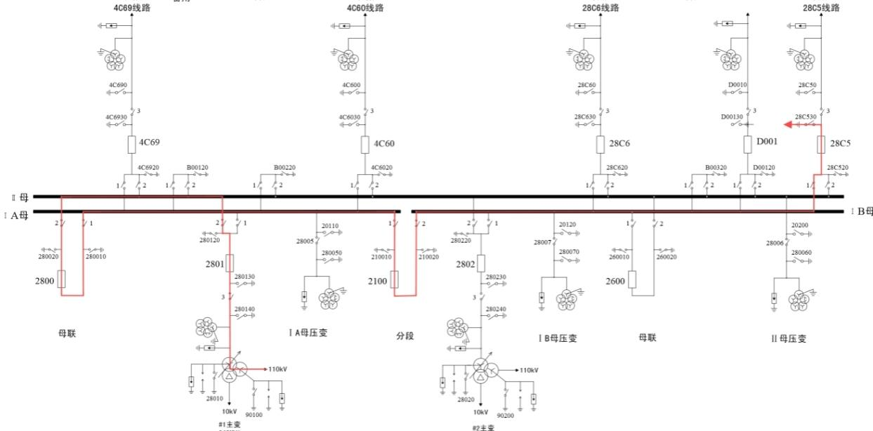
△ High-Voltage Side
In the figure above, for the CT of the main transformer high-voltage side bay, P1 points to the busbar, and the current flows from P2 to P1— the secondary current angle is 90° positive sequence. For the CT of the outgoing line bay, P1 points to the busbar, and the current flows from P1 to P2— the secondary current angle is 270° positive sequence.
- Current Injection from Medium-Voltage Side (110kV) to Low-Voltage Side (10kV)
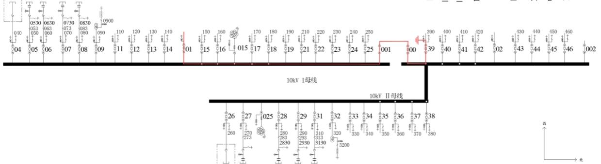
△ Low-Voltage Side (Main Transformer Y-Y-Δ Connection)
In the figure above, for the CT of the low-voltage side main transformer bay, P1 points to the busbar, and the current flows from P2 to P1— the current is 180° out of phase with the voltage. In addition, due to the Y-to-Δ conversion, the current leads the voltage by 30°; thus, the secondary current angle of the low-voltage side main transformer bay is 270° + 180° + 30° = 120° positive sequence. For the CT of the low-voltage side bay, P1 points to the busbar, and the current flows from P1 to P2— the current-voltage angle is 270° + 30° = 300° positive sequence.
△ Angle of Main Transformer High-Voltage Side Protection Device
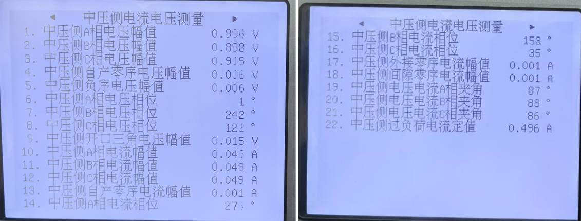
△ Angle of Main Transformer Medium-Voltage Side Protection Device
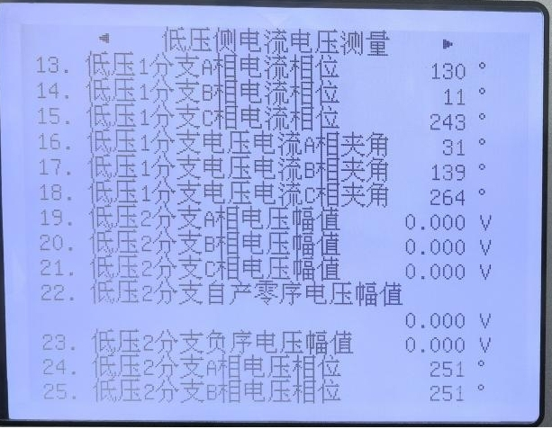
△ Angle of Main Transformer Low-Voltage Side Protection Device
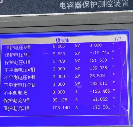
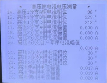
△ Angle of Low-Voltage Side Capacitor Measurement and Control Device
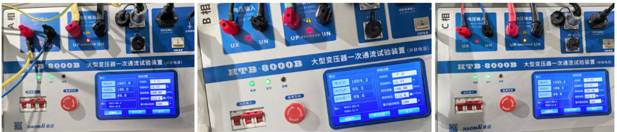
△ Parameter Setting
24-hours hot line 400-099-8859 technical hot line: 13971234137

Copyright © 2024 All rights Reserved.
备案号:鄂ICP备05010718号-1
