Contact: sales@haomai.net
NEWS
Company News
Case Practice | Method and Application of Load Simulation-based Relay Protection Vector Check
When substation protection devices are newly installed or there are modifications to current and voltage circuits, a load-carrying vector check test must be conducted before commissioning to verify the correctness of wiring. This step prevents differential current imbalance caused by vector errors in transformers or lines, which could lead to maloperation of protection devices and disrupt the normal operation of lines.
Although it is feasible to perform the vector check test by adjusting the operation mode to organize power flow in some cases, this approach requires multiple adjustments to the power grid operation mode (e.g., switching from double-bus to single-bus operation), which may affect the reliable operation of the power grid. In addition, prior to conducting the vector check test, it is necessary to formulate a commissioning plan. After confirmation by dispatchers, an order will be issued to implement the operation mode adjustment of the power grid, and operation personnel need to cooperate with a series of complex operations such as switching operations. This process requires a large number of personnel, involves heavy workload, takes a long time, and may entail operational risks.
Wuhan Haomai has proposed a new method for load simulation-based relay protection vector check. This method applies electrical quantities using test equipment to conduct current and voltage injection on line bays or main transformer devices, verifying the correctness of vectors in the primary and secondary circuits.
Test Equipment
HTA-3300 Three-phase Digital Intelligent High-current Source,HTV-6000 Three-phase Digital Intelligent High-voltage Source,YD-300E Intelligent Current & Voltage Source Wireless Remote Control Host
△ HTA-3300 Three-phase Digital Intelligent High-current Source
△ HTV-6000 Three-phase Digital Intelligent High-voltage Source
Advantages Compared with Traditional Load Simulation-based Vector Check Methods
Flexible and Editable Output Parameters:The amplitude and phase of output current for each phase are adjustable. The HTA-3300 Three-phase Digital Intelligent High-current Source can output three-phase current ranging from 0 to 300A with an editable phase angle of 0–360°. The HTV-6000 Three-phase Digital Intelligent High-voltage Source can output three-phase voltage ranging from 0 to 6000V with an editable phase angle of 0–360°.
Diversified Synchronization Modes:The equipment supports multiple synchronization modes, including external voltage synchronization, GPS synchronization, and remote wireless remote control synchronization. It controls equipment output by taking the same voltage reference in the substation, enabling the current source and voltage source to output with the same frequency and phase as the system. This simulates real load flowing through CT/PT, and wireless remote control output makes the operation simpler.
Modular Design:For different application scenarios, the equipment can be configured according to on-site requirements, featuring a more compact size and easier operation.
On-site Case
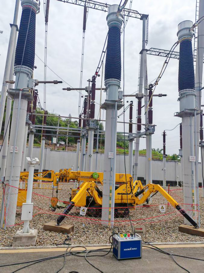
A power supply company replaced the bus tie switch CT of a 220kV substation and needed to verify the correctness of wiring polarity of the CT connected to the busbar protection. A load simulation-based test was adopted to verify the polarity before commissioning.
Test Equipment: HTA-3300 Three-phase Digital Intelligent High-current Source, YD-300E Intelligent Current & Voltage Source Wireless Remote Control Host
1. Pre-test Preparation
No other line test work shall be carried out at the test site. The secondary side of PT shall not be short-circuited, and the secondary side of CT shall not be open-circuited. The equipment connection point must have access to a power supply.
During the work, the 220kV I-II Bus 1# and 2# Busbar Protection Devices need to be shut down in turns. Improper implementation of secondary safety measures for non-current-injection CT windings may cause the in-service busbar protection devices to operate.
Confirm that all trip outlet and failure initiation hard press plates in the bus differential protection panel to be tested have been withdrawn.
2. Test Wiring
HTA-3300 Three-phase Digital Intelligent High-current Source Wiring
The primary test line shall be reliably connected to the polarity terminal P1 of the primary side of the bus tie 212 switch CT. The primary current flows out from P2 after passing through the CT, forming a reliable loop of "P1 — CT — P2". On-site, the A/B/C phases of the current source are respectively connected to the P1 side of each phase of the bus tie switch CT, the P2 side is three-phase short-circuited and grounded, and the N line of the current source is clamped to the ground bar to form a current loop.
△ Current Source Wiring
Voltage Reference Wiring
Take the AN phase voltage of the test busbar protection device as the reference and connect it to the voltage terminal of the YD-300E.

△ Voltage Reference Wiring
3. Parameter Setting
Taking the 220kV I-II Busbar Protection 1# Panel as an example, select a branch with small load current in the panel as the reference. Through observation, the Wentian 1st Line bay on Bus II is selected, with a load current of 240A and a positive-sequence phase angle of 12°. Short-circuit the current of this branch at the terminal block inside the busbar protection panel (at this time, differential current will appear in the 220kV I-II Bus 1# Busbar Protection Device, and this differential current value is the load current of the short-circuited branch; Element 8 shows the current status inside the Busbar Protection 1# Panel after the branch is short-circuited). The load status of the selected branch and the differential current value on the busbar protection after short-circuit are shown in the figures below.
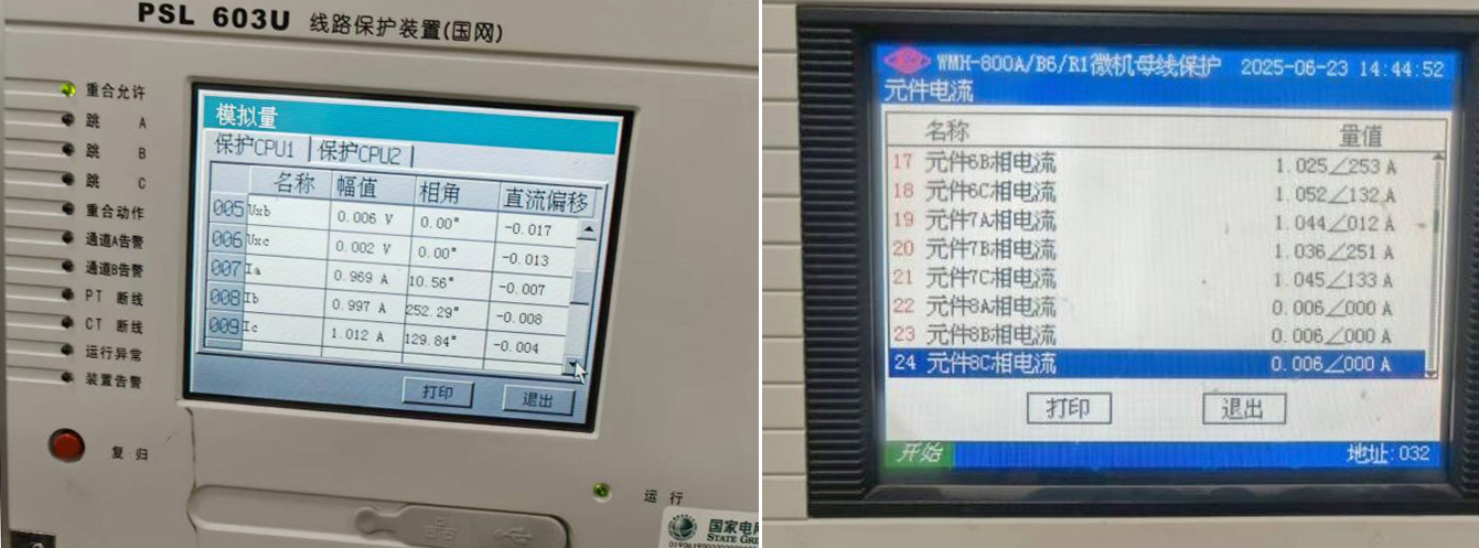
△ Display Value of Wentian 1st Line Protection Device
△ Differential Current Display Value of I-II Busbar Protection 1# Panel After Short-circuit
The transformation ratio of the Wentian 1st Line bay is 1200/5, and that of the 212 bus tie bay is 2500/5. The differential value is displayed based on the transformation ratio of 2500/5. It can be seen that:
Before short-circuiting, the secondary current value of the Wentian 1st Line bay is about 1A, which is converted to a primary value of approximately 240A, and the differential current of the major differential protection is basically 0.
After short-circuiting, the secondary current value of the Wentian 1st Line bay is 0, the major differential current is 0.460, the minor differential current of Bus II is approximately 0, and the minor differential current of Bus I is 0.460, which is consistent with the actual situation.
Use the HTA-3300 to inject current simulating the current of this bay into the bus tie switch CT:Set the HTA-3300 operation mode to remote control mode.Search for the corresponding device using the YD-300E.After connection is completed, set the output amplitude and phase angle to be consistent with those of the Wentian 1st Line.Return to the remote control main interface and click Start to control the connected device for output.
Injected Value and Protection Device Display Result:
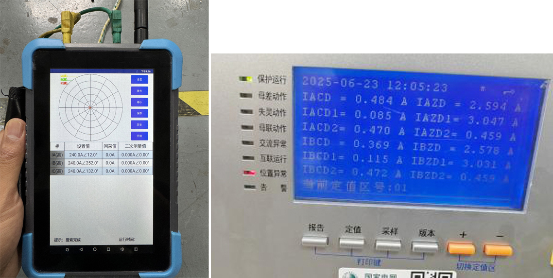
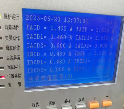
△ Busbar Protection Differential Current Value After Injection of Current with Same Amplitude and Phase Angle
Next, set the output to have the same amplitude but a phase angle opposite to that of the Wentian 1st Line by 180°, then return to the remote control main interface and click Start to control the connected device for output.
Injected Value and Protection Device Display Result:

△ Bus Differential Protection Differential Current Display Value After Injection of Current with Same Amplitude and 180° Opposite Phase Angle
- Test Result Analysis
|
Item |
Primary Current Direction |
Phase |
Actual Line Value (V,A) / Set Output Amplitude (V,A) |
Actual Line Angle (°) / Set Output Angle (°) |
Ratio & Polarity |
Calculated Secondary Value (A) |
|
Actual Secondary Value (A) |
|
Bus Protection Differential Current |
|
|
|
|
|
|
|
Amplitude |
Angle |
Amplitude |
Angle |
|
|
220kV/Wentian 1 Line Protection Device (Wentian 1 Line Short-circuited on Bus Protection Device) |
P1 → P2 |
A |
240 |
11 |
1200/5 |
— |
— |
0.969 |
11 |
Bus Differential: 0.460 I Bus Differential: 0.460 II Bus Differential: 0 |
|
|
|
B |
240 |
252 |
|
— |
— |
0.997 |
252 |
|
|
|
|
C |
240 |
130 |
|
— |
— |
1.012 |
130 |
|
|
Bus Protection Device 1 (Same Angle Output as Wentian 1 Line) |
P1 → P2 |
A |
240 |
12 |
2500/5 |
0.480 |
12 |
0.472 |
10 |
Bus Differential: 0.480 I Bus Differential: 0.085 II Bus Differential: 0.470 |
|
|
|
B |
240 |
252 |
|
0.480 |
252 |
0.475 |
251 |
|
|
|
|
C |
240 |
132 |
|
0.480 |
130 |
0.473 |
131 |
|
|
Bus Protection Device 1 (180° Reverse Output to Wentian 1 Line) |
P1 → P2 |
A |
240 |
192 |
2500/5 |
0.480 |
192 |
0.475 |
193 |
Bus Differential: 0.503 I Bus Differential: 0.980 II Bus Differential: 0.478 |
|
|
|
B |
240 |
72 |
|
0.480 |
72 |
0.476 |
74 |
|
|
|
|
C |
240 |
312 |
|
0.480 |
312 |
0.478 |
309 |
|
The bus tie switch is not involved in the calculation of the major differential current, and the Wentian 1st Line is connected to Bus I. If the wiring of the 212 bus tie switch CT is correct:
When current with the same amplitude and phase angle is injected in this way, the minor differential current of Bus I should be offset.
When current with the same amplitude but a 180° opposite phase angle is injected, the minor differential current of Bus I should be doubled to the initial value.
It can be seen from the above data that:
When a 240A current is injected into the primary side with the same phase angle as the Wentian 1st Line, the minor differential current of Bus I of the busbar protection returns to 0A.
When a 240A current is injected into the primary side with a phase angle 180° different from that of the Wentian 1st Line, the minor differential current of Bus I of the busbar protection doubles the previous value.
Therefore, the test result is correct, and it can be concluded that the vector of the 212 bus tie bay connected to the 220kV I-II Busbar Protection 1# Panel is correct.
24-hours hot line 400-099-8859 technical hot line: 13971234137

Copyright © 2024 All rights Reserved.
备案号:鄂ICP备05010718号-1
