Contact: sales@haomai.net
NEWS
Company News
Case Practice | Vector Check of Line Differential Protection for 220kV AB Substation
Line reconstruction and expansion are usually carried out on both sides of the line simultaneously. The traditional method generally involves self-looping of the local side protection device and applying quantity on a single side to verify the vector of backup protection, which makes it difficult to verify the vector of differential protection. State Grid Corporation's Q/GDW 12690-2025 Test Guidelines for Load Simulation-based Relay Protection Vector Check clearly specifies the vector check method for line differential protection of AB Substation. Both substations take the system power supply as the reference (or adopt time synchronization), and use test equipment to simulate the primary load current flowing through the current transformer respectively, so as to check whether the vector of line differential protection is correct.
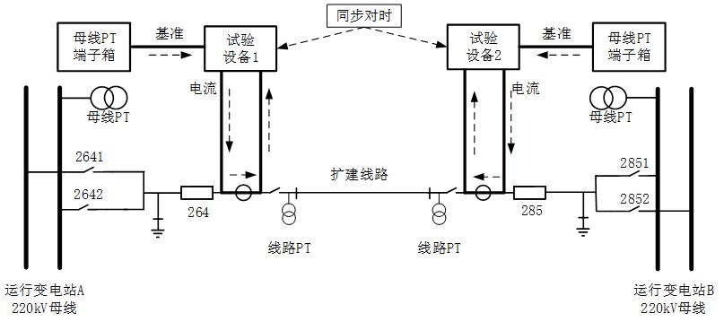
This article introduces the use of HTA-3300 Three-phase Digital Intelligent Current Source to conduct the vector check of differential protection for AB Substation by means of time synchronization.
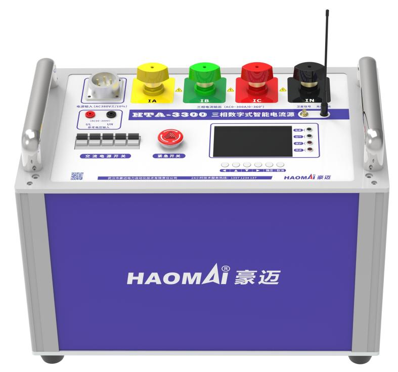
△ HTA-3300 Three-phase Digital Intelligent Current Source
CT replacement was carried out at the 2212 bay of a 220kV substation, and synchronous CT replacement was performed at the 2211 bay of a wind farm on the opposite side. Before power transmission, a load simulation-based relay protection vector check was conducted, and one HTA-3300 Three-phase Digital Intelligent Current Source was prepared for each side.
1. Test Wiring
Since both substations adopt AIS overhead wiring, the test on the substation side uses a three-phase current source to perform primary current injection at the CT of 2212 bay. The three-phase output lines of the test equipment are respectively clamped at the P1 position of the three-phase current transformer for current injection. After passing through the current transformer, a primary three-phase short-circuit wire is used for short-circuit connection to the N terminal of the current-carrying equipment to realize current return (if conditions permit, the current can be returned through the earthing switch). The scope of the current-carrying path should be minimized to avoid impact on the operating system.
For the test on the wind farm side, a three-phase current source is used for primary current injection at the CT of 2211 bay. The three-phase output lines of the test instrument are directly clamped at the P1 position of the three-phase current transformer for current injection. After passing through the current transformer, a primary three-phase short-circuit wire is used for short-circuit connection to the N terminal of the current-carrying equipment to realize current return. The scope of the current-carrying path should be minimized to avoid impact on the operating system.
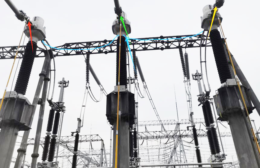
△ On-site Wiring
2. Test Method
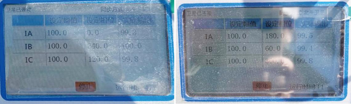
After the test equipment is powered on, select the GPS time synchronization mode, and time synchronization between the two substations can be achieved through GPS. After time synchronization, the current source on the substation side outputs primary applied current of 100A ∠ 0 ° for phase A, 100A ∠ 240 ° for phase B, and 100A ∠ 120 ° for phase C respectively. The current source on the wind farm side outputs primary applied current of 100A ∠ 180 ° for phase A, 100A ∠ 60 ° for phase B, and 100A ∠ 300 ° for phase C respectively. Synchronous triggering is realized through the second pulse to ensure the phase synchronization of current output on both sides at the zero-crossing moment. Check the sampling data and differential current on the protection device to complete the vector verification test of line differential protection.
3. Test Results
After the current is injected, check the sampling information on the protection device.
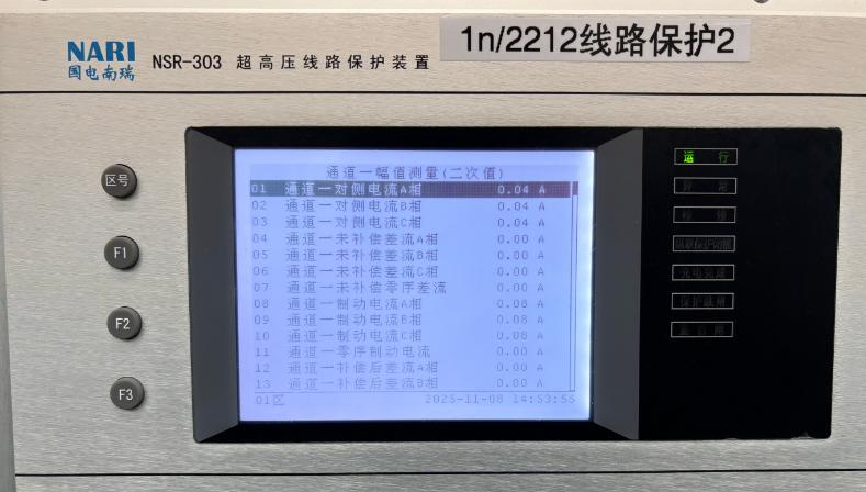
△ Sampling Data of Line Protection Set A on the Substation Side
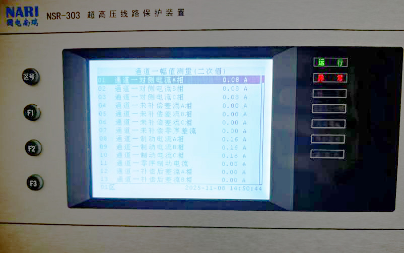
△ Sampling Data of Line Protection Set A on the Wind Farm Side
On-site test data:
|
Protection Device |
Current/Voltage Channel |
Circuit No. |
Transformation Ratio |
Phase A (A) |
Phase B (A) |
Phase C (A) |
|
Substation-side LineProtection NSR-303A |
Local-side Current |
|
2500/1 |
0.04 |
0.04 |
0.04 |
|
Opposite-side Current |
|
1250/1 |
0.04 |
0.04 |
0.04 |
|
|
Differential Protection Operating Current |
0 |
0 |
0 |
|||
|
Differential Protection Restraining Current |
0.08 |
0.08 |
0.08 |
|||
|
Wind Farm-sideLine Protection NSR-303A |
Local-side Current |
|
2500/1 |
0.08 |
0.08 |
0.08 |
|
Opposite-side Current |
|
1200/1 |
0.08 |
0.08 |
0.08 |
|
|
Differential Protection Operating Current |
0 |
0 |
0 |
|||
|
Differential Protection Restraining Current |
0.16 |
0.16 |
0.16 |
|||
The actual current-carrying direction on the substation side is from the busbar to the line, and the actual current-carrying direction on the wind farm side is also from the busbar to the line. The current displayed by the protection device is the converted current, and the differential current is 0, indicating that the vector of the line differential protection is correct.
24-hours hot line 400-099-8859 technical hot line: 13971234137

Copyright © 2024 All rights Reserved.
备案号:鄂ICP备05010718号-1
