Contact: sales@haomai.net
NEWS
Company News
Case Practice | Load Simulation-based Relay Protection Vector Check for ±800 kV Converter Station
Enterprise News
Case Practice | Load Simulation-based Relay Protection Vector Check for ±800 kV Converter Station
Release Date: November 21, 2025Wuhan Haomai Electric Power Automation Co., Ltd.
When a new substation protection device is installed, a load-carrying vector check test must be conducted before commissioning to verify the correctness of wiring. This step prevents differential current imbalance caused by transformer vector errors, which could lead to maloperation of protection devices and disrupt the normal operation of lines.
Although it is possible to carry out the vector check test by adjusting the operation mode to organize power flow in some cases, this requires multiple adjustments to the power grid operation mode (e.g., switching from double-bus to single-bus operation), which may affect the reliable operation of the power grid. In addition, before performing the vector check test, it is necessary to formulate a commissioning plan. After confirmation by dispatchers, an order will be issued to adjust the power grid operation mode and carry out commissioning operations. Operation personnel need to cooperate with a series of complex tasks such as switching operations. This process requires a large number of personnel, involves heavy workload, takes a long time, and may entail operational risks.
The load simulation-based relay protection vector check test method applies voltage and current from the primary side using dedicated equipment to conduct current and voltage injection on the main transformer device, verifying the correctness of vectors in the primary and secondary circuits.
Test Device: HTB-8000 Large Transformer Primary Current Injection Test DeviceTest Mode: Three-phase current and voltage injection on the valve side, with the grid side short-circuited and grounded. The current injection bays cover the Y/Y and Y/D phase-splitting converter transformers in the Valve Hall 1 High and Valve Hall 2 High.
Analysis of Transformer Nameplate Parameters
In the mode of current injection on the grid side with the valve side short-circuited and grounded, the grid-side current is too small to achieve the test objectives. Therefore, the test adopts current injection on the valve side with the grid side short-circuited and grounded.Between the Y/D and Y/Y connection modes, the rated voltage level of the valve side in Y/Y mode is  times higher than that in Y/D mode. Consequently, the impedance of the Y/Y mode (5Ω) is lower than the minimum required compensation impedance (6.5Ω), and a series reactor must be connected to increase the loop impedance.For the Y/D mode, since there is no √3 factor on the valve side but a
  factor exists on the grid side, calculating the induced current using the current ratio yields a more accurate primary current value compared with the calculation based on the voltage ratio.
Current Injection Test
- Power Supply for the Device

△ Power Extraction at the Maintenance Box Power Supply
- Application of Reference Voltage

△ Power Supply Box Near the PT Terminal Box △ Three-phase Voltage Extraction from the Power Supply Box

△ PT Terminal Box △ Secondary Reference Voltage Injection into the PT Terminal Box △ Reference Voltage Box
The HTB-8000 Large Transformer Primary Current Injection Test Device takes the phase A voltage from the power extraction point (the substation maintenance box power supply) as the reference. The opposite side (grid side), which is short-circuited and grounded, has no primary voltage but only primary current. Therefore, it is necessary to output a secondary homologous reference voltage to the secondary side of the protection device on the opposite side (grid side), with the phase A voltage of the maintenance box power supply as the reference.
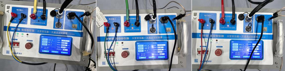
- Current Injection for Y/Y Mode in Valve Hall 1 High

A current of 100A is injected into the YY connection on the valve side of the high-voltage end, with an induced current of 22A on the grid side. For the YY connection mode, the device only needs the neutral line to be connected to the ground bar. Close the earthing switch of the valve hall, and connect phases A/B/C of the device to the corresponding bushings respectively to form a loop.A series reactor must be connected for current injection in the YY mode. The short-circuit impedance parameters can be deduced based on the actual impedance after the reactor is connected in series, or calculated by adding the impedance of the YY-connected converter transformer to the nameplate impedance of the reactor.

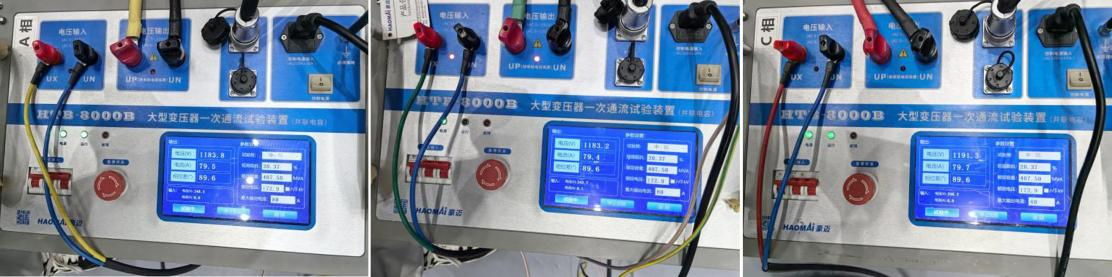
- Current Injection for Y/D Mode in Valve Hall 2 High


A current of 80A is injected into the YD connection on the valve side of the high-voltage end, with an induced current of 30A on the grid side.For the YD connection mode, the valve side adopts a delta connection, where the tail end of phase B is connected to the head end of phase A, the head end of phase B is connected to the tail end of phase C, and the head end of phase C is connected to the tail end of phase A. Therefore, it is necessary to disconnect the Bn-phase, Cn-phase, and C-phase bushings. At the Bn-phase bushing, clamp the phase A terminal of the device to the head end of phase A on the valve side, and clamp the Bn terminal of the device to the tail end of phase B, and so on for the other phases.
The entire test process was completed efficiently and in an orderly manner, with all test data being accurate. It provided data support for verifying the correctness of converter transformer wiring and effectively ensured the smooth commissioning of the Valve Hall 1 High and Valve Hall 2 High of the converter transformer.
24-hours hot line 400-099-8859 technical hot line: 13971234137

Copyright © 2024 All rights Reserved.
备案号:鄂ICP备05010718号-1
