Contact: sales@haomai.net
NEWS
Company News
Case Practice | Vector Verification for Bus Differential Protection During Line Connection in 220kV Operating Substation Expansion and Reconstruction
Before commissioning newly expanded or reconstructed lines in an operating substation, load transfer operations are often difficult to perform. When connecting these lines to bus differential protection, it is therefore challenging to confirm whether the vector relationships are correct. If the vectors are incorrect, it may directly cause bus differential protection maloperation, leading to very serious consequences. The State Grid Corporation of China standard Q/GDW 12690-2025 “Guidelines for Load-Simulation Relay Protection Vector Verification Tests” clearly specifies methods for vector verification when newly expanded or reconstructed lines are connected to bus differential protection.
When performing bus protection vector verification, a bus differential protection “rotation-out” method is adopted. For the bus protection that is taken out of service, an appropriate current branch is selected as the reference. The current of this branch is short-circuited at the bus protection terminal block. At this time, the primary differential current of the bus protection equals the primary current of the reference branch. A primary current with the same magnitude and phase as the reference branch is injected into the newly constructed bay, and the differential current of the bus protection should be 0. Then, a primary current with the same magnitude but opposite phase is injected, and the primary differential current of the bus protection should be twice the primary current of the reference branch. This method is known as the branch substitution method. If the above conditions are satisfied, the vector verification is considered correct. After the test, appropriate safety measures must be taken and the bus protection restored, and the same method is used to check the other set of bus protection.
The following introduces the use of the HTA-3300 three-phase digital intelligent high-current source, adopting a method synchronized with the system voltage as the reference, to perform vector verification for bus differential protection when newly expanded or reconstructed lines are connected.
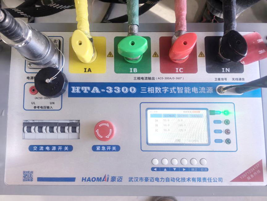
△ HTA-3300 Three-Phase Digital Intelligent High-Current Source
A certain 220kV substation adopts a GIS primary structure. A new 2214 bay has been expanded and all on-site commissioning has been completed. Before energization, the conditions meet the requirements for simulated load relay protection testing.
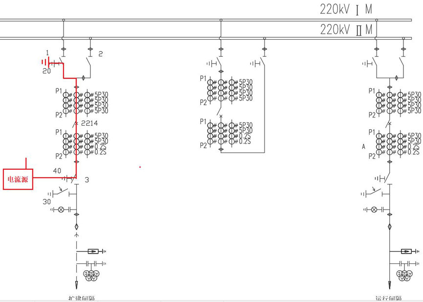
1. Test Wiring
Since the bus is in operation, multi-bay series current injection cannot be used; only single-bay current injection is possible. The ABC three-phase current from the current source is injected from the grounding switch 221440 of the expanded line (passing through the CT), flows through breaker 2214, and enters the ground via grounding switch 221420. The N phase of the current source is grounded to form the current loop. At the same time, the current source uses the system voltage A-phase from the bus voltage transformer terminal box (the metering PT A-phase winding can be used) as the reference, and synchronously outputs three-phase primary current (this current should be determined based on the magnitude and power flow direction of the short-circuited reference branch). Sampling magnitude, phase, and differential current are observed on the line protection device and the rotated-out bus protection to determine whether the vectors of the line backup protection and the connected bus differential protection are correct.
2. Test Method
Specific operating procedure:
- Issue a work permit and implement secondary safety measures.
2) Check the position status of switches and disconnectors in the expanded 2214 bay as shown in the table.
|
Sequence |
Switch Disconnector |
Position Status |
Verification |
|
1 |
Circuit Breaker: 2 214 |
Closed Position |
|
|
2 |
Isolating Switch: 2 2141/22142/22143 |
Open Position |
|
|
3 |
Earthing Switch: 2 2142 0/2 2143 0/2 2144 0 |
Closed Position |
|
|
4 |
Other Unspecified Circuit Breakers, Earthing Switches and Isolating Switches |
Open Position |
|
3) Remove the grounding copper bar of grounding switch 221440 as the current injection point (flowing toward the breaker), select grounding switch 221420 as the current entry point, and ground the N phase of the test device.
4) Take voltage for the protection devices from the bus PT. At the rear of the line protection panel, introduce the bus voltage into the line protection by short-circuiting the bus disconnector position contact (22141 disconnector), ensuring that the line protection device has secondary voltage and a reference for current sampling.
5) Reconfirm that none of the CT windings under test in the CT terminal box are open-circuited. Ensure that the current flowing into the in-service set B bus differential protection is short-circuited and isolated.
6) Select a lightly loaded operating line as the reference branch. Short-circuit it at the rear of the out-of-service set A bus differential protection panel and isolate it to ensure that the branch current does not flow into set A. Observe the sampling in the set A bus differential protection device, where differential current should appear. Measure and calculate the primary current magnitude and power flow direction of the reference branch. On the bus differential simulation panel, force the operating branch disconnector onto the same bus as the reference branch.
7) In the bus PT terminal box, connect the A-phase voltage of the metering circuit to the external voltage detection input of the current source, using this voltage as the reference to control synchronous current output.
8) After completing the above operations, first output a small current from the current source to check whether the circuit is correct. Then, using the system voltage A-phase as the reference, output current with the same magnitude and phase as the reference branch. Observe sampling on both sets of line protection devices and the out-of-service set A bus protection device, analyze the test data, and draw conclusions.
9) After completing the test, verify absence of voltage, remove the test leads, and restore the switch and disconnector states according to the secondary safety measures.
10) Use the same method to perform vector verification for the expanded line connected to set B bus differential protection.
3. Test Results
After completing all test preparations, the measured secondary current magnitude and power flow direction of the short-circuited operating reference branch are:
Phase A: 0.13 A ∠ 28°,Phase B: 0.14 A ∠ 268°,Phase C: 0.12 A ∠ 148°.
The current ratios of both the test branch and the reference branch are 2000/1. The calculated three-phase primary current applied by the current source is:
Phase A: 26 A ∠ 208°,Phase B: 26 A ∠ 88°,Phase C: 26 A ∠ 328°.
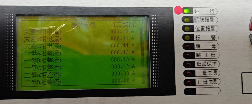
Before short-circuiting the operating reference branch, the large differential current on the bus differential protection is 0. After short-circuiting, the three-phase differential current observed is 0.25 A. After confirmation, the three-phase primary current is quickly output according to the calculated values, at which time the differential current on the bus protection is 0. Then, the phase of the applied three-phase primary current is reversed by 180°, namely:
Phase A: 26 A ∠ 28°,Phase B: 26 A ∠ 268°,Phase C: 26 A ∠ 148°.
After operation, the three-phase differential current on the bus protection is 0.25 A. Based on this, it is determined that the vector polarity of the expanded branch connected to the bus differential protection is correct.

△ Differential Current After Short-Circuiting the Reference Branch
△ Apply Differential Current Consistent with the Reference Branch
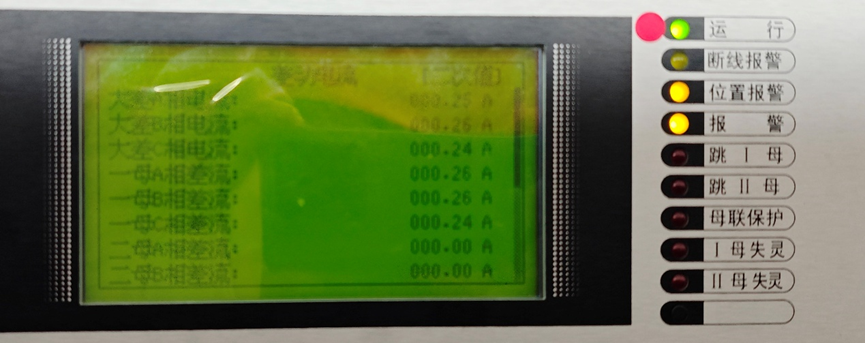
△ Apply Differential Current Opposite to the Reference Branch
For 220kV line protection, the CT polarity terminal is on the bus side. Since the bus-side grounding switch is a safety grounding, the current injection direction is from the line side to the bus side. The through current flows into the non-polarity terminal and out of the polarity terminal. When the current source output is set to 0°, the protection sampling should be 180°. This 180° phase difference should be noted when analyzing test results. Only when the direction of the current applied by the current source differs by 180° from the reference branch will the differential current be 0. Special attention must be paid to ensure that the CT current of the expanded bay does not flow into the in-service bus differential protection, and that secondary safety measures are strictly implemented.
24-hours hot line 400-099-8859 technical hot line: 13971234137

Copyright © 2024 All rights Reserved.
备案号:鄂ICP备05010718号-1
