Contact: sales@haomai.net
NEWS
Company News
KV bus section switch load analog vector check
The 220V II-IV bus section 224 switch of a station is replaced with CT. If the wrong wiring of CT connected to the bus differential protection results in reverse polarity connection, the bus differential protection may malfunction. In order to reduce the power grid operation risk and switching operation risk, the test and verification of the secondary current circuit of the 224 switch CT of the 220kV II-IV bus section are completed by one-time current passing. The current circuit of the 224 switch bay of the 220kV I-II and III-IV bus 1 and 2 protection is checked by load simulation to check the correctness of the phase and amplitude of the current and voltage flowing into the protection device and the relative polarity relation of the current transformer primary wiring, so as to ensure the correctness and completeness of the secondary current circuit.
Test equipment: HTA-3300 three-phase digital intelligent large current source, YD-300E intelligent current and voltage source wireless remote control host
There shall be no staff at the test site for line test. PT shall not be short-circuited at the secondary side and CT shall not be open-circuited at the secondary side. The access point of test equipment shall be provided with power supply. During the test, 220kV I-II and III-IV bus 1 # and 2 # protection devices shall be stopped in turn. Improper implementation of secondary safety measures for non-current CT winding may cause operation of bus protection device. Confirm that all trip outlets and failure startup pressing plates in the busbar differential protection panel have been deactivated.
The primary test line of HTA-3300 three-phase digital intelligent large current source shall be reliably connected to the polarity terminal P1 of the primary side of the sectional 224 switch CT, and the primary current flows out from P2 after passing through CT to form a "P1-CT-P2" reliable circuit (see the figure below).
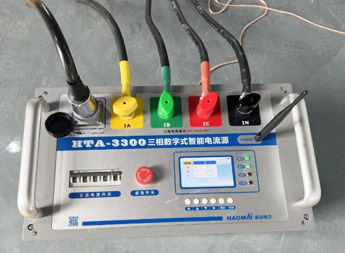
△ HTA-3300 Three-phase Digital Intelligent Large Current Source Wiring
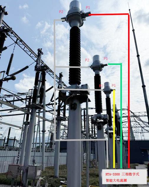
△ HTA-3300三相数字智能大电流源接线
Voltage reference wiring:
Take the AN phase voltage of the busbar differential protection device as the benchmark, and connect it to the voltage terminal of the wireless remote control host of the YD-300E intelligent current and voltage source (see the figure below).
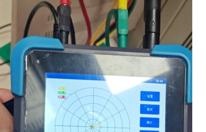
Taking 220kV I-II bus protection panel 2 as an example, select a group of branch circuit with small load current in panel 2 as the benchmark. Through field observation, the 262 interval on bus II is appropriate. Short-circuit the current of the branch circuit in the terminal block of the protection panel (at this time, the protection device of 220kV I-II bus 2 will have differential current, and the secondary differential current value is the primary load current of the short circuit branch). The differential current value and branch current on the protection before and after short circuit are shown in the following figure.
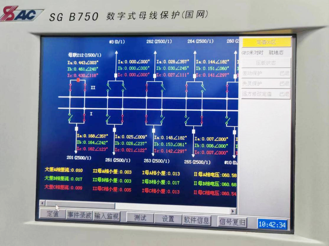
△Display value of No. 2 screen of 220kV I-II busbar protection before short circuit
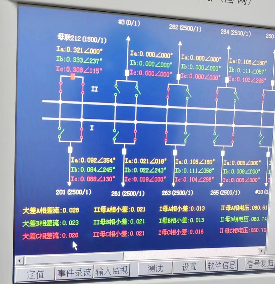
△Display value of No. 2 screen of 220kV I-II busbar protection after short circuit
The interval transformation ratio of 262 is 2500/124The sectional interval is 4000/1, and the differential value display reference is 4000/1. It can be seen that:
Before short circuit, the interval secondary current value of 262 is about 0.026A, which is converted into the primary value of about 65A, the big difference is 0.01, the small difference of bus II is about 0.003, and the small difference of bus I is 0.013.
The interval secondary current value of 262 after short circuit is 0, the big difference is 0.028, the small difference of bus II is about 0.021, and the small difference of bus I is 0.013.
Simulate the bay current with HTA-3300 three-phase digital intelligent large current source
Select HTA-3300 operation setting as remote control mode, search corresponding equipment with YD-300E, set output amplitude and angle after connection, return to remote control main interface, click "Start" to control connected device for output.
See the following figure for the display results of dosing value and protection device:

△ Secondary current value of 224 interval after dosing
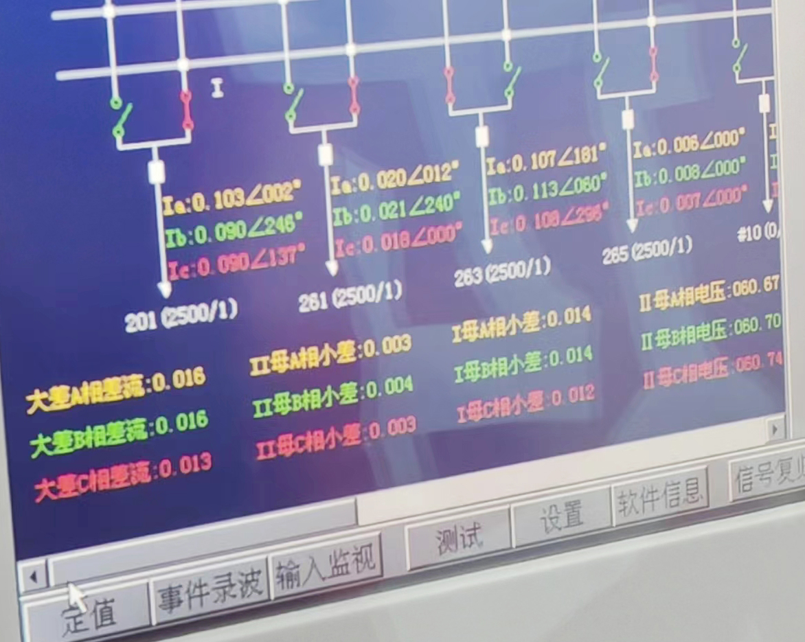
△ Display value of differential current of busbar differential protection after being connected to bay 224 current
| KV I-II bus protection panel 2 | 224Bay | 262 bay | differential | II bus differential | I busdifferential |
| Short-circuit 262 data before interval | 0A | 0.026A | 0.01A | 0.003A | 0.013A |
| Short-circuit 262 data after interval | 0A | 0A | 0.028A | 0.021A | 0.013 |
| Data after accessing 224 bay current | 0.016A | 0A | 0.013 | 0.003A | 0.013 |
If the installation and wiring of 224 section switch CT are correct, the differential current shall be able to offset in this way. It can be concluded from the above table that when the angle of 65A and voltage difference of 180 ° are applied at the primary side, the differential current value generated by short-circuiting bay 262 is reset to 0A again (the differential current of one point on bus I is not reset to 0). The final displayed large difference and small difference of bus II are close to 0, so the result is correct. Therefore, the vector from the 224 section bay to the 220kV I-II bus protection panel 2 is correct.
Copyright © 2024 All rights Reserved.
备案号:鄂ICP备05010718号-1


