Contact: sales@haomai.net
NEWS
Company News
Transformer test technology for distribution automation terminal
The rapid development of power distribution automation puts forward new and higher requirements for power distribution safety and reliability, and the daily operation and maintenance of power distribution system become the top priority. There are a large number of terminal transformers in the distribution network, many manufacturers, and the operation and maintenance are cumbersome. Some users regularly replace or replace after failure according to the service life, which lacks the predictability or causes waste, and affects the operation stability of the distribution system to a certain extent.
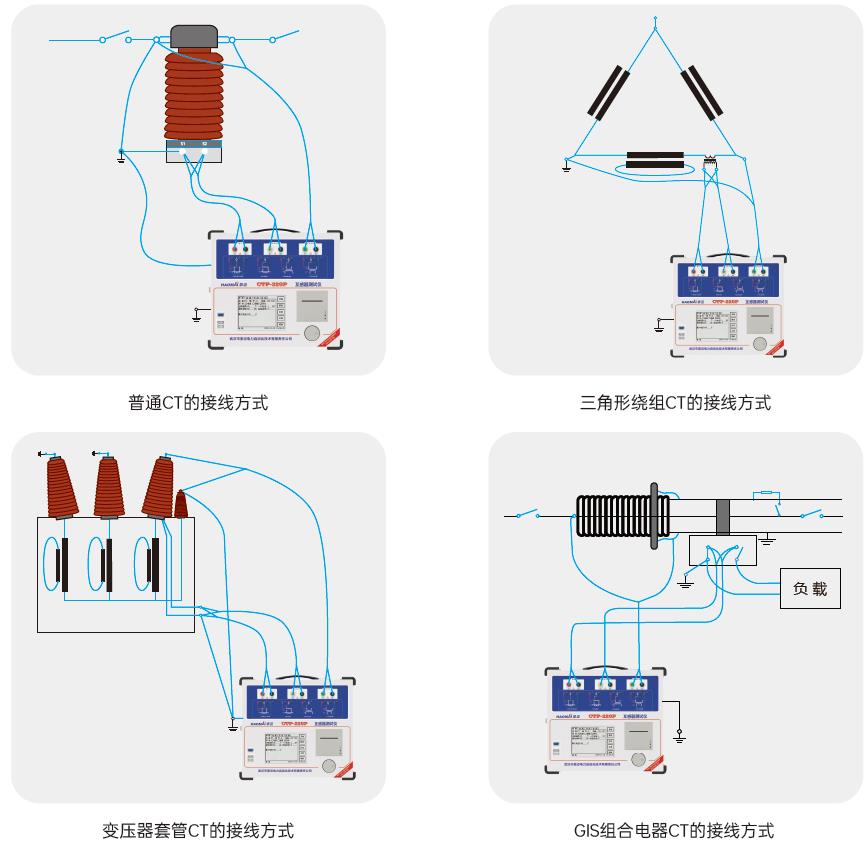
CTP-220 transformer tester is used to complete the comprehensive characteristic test of all transformers. This tester adopts the latest square wave method technology, and the test time is shortened by about 50% compared with the traditional tester. It can complete the excitation characteristic, transformation ratio, polarity, secondary winding resistance, secondary load, ratio difference and angle difference tests of all types of CT, such as protection type, metering type and TP type. It can perform the characteristic test of all types of PT electromagnetic units, and can test CT with inflection point up to 30kV. It is simple in wiring, one-touch test, efficient and stable. The equipment will automatically give the inflection point voltage/current, 10% (5%) error curve, accurate limit factor (ALF), instrument security factor (FS), secondary time constant (Ts), remanence coefficient (Kr), saturated and unsaturated inductance and other parameters. The software will automatically analyze the data and generate the test report.

△ CTP Transformer Tester Wiring Diagram
In order to further improve the technical skills of transformer test of distribution network, the power supply company organized the professional training of distribution network automation and specially offered relevant courses of transformer technology. Wuhan Halma was invited to deeply communicate with the site technical personnel about the transformer principle, transformer test technology and test results analysis, etc. The site response was lively. Combined with the problems encountered in the operation and maintenance, we actively asked questions, focusing on accurate present value coefficient, inflection point voltage, error curve, secondary load and other issues, and got a lot of ideas.

-
Determination of accurate limit factor (ALF): the measured value is greater than or equal to the rated value.
For protection CT, the ratio of rated accuracy limit primary current to rated primary current, i.e. 5P10 and 10P20. The accuracy limit coefficient is followed by P value. The common accuracy limit coefficient is 5, 10, 20, 25, 30 and 40.Excitation characteristic judgment: the knee point voltage is greater than the limiting electromotive force.
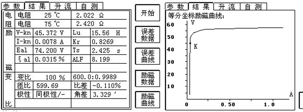
The inflection point is the saturation point of the voltage-current characteristic curve (iron core magnetization curve). When the voltage at the inflection point increases by 10%, the current at the inflection point increases by 50%. The voltage at the inflection point is required to be greater than the limiting electromotive force. According to the requirements, K=√ 2. The distribution network system requires that the CT inflection point voltage is greater than the limiting electromotive force. If the conditions are not met, the composite error requirements may be not met, and CT operates in the linear section, causing misoperation, etc.

△Excitation Characteristic Results
- Error characteristic curve judgment: the measured value is far less than the calculated value (error curve).
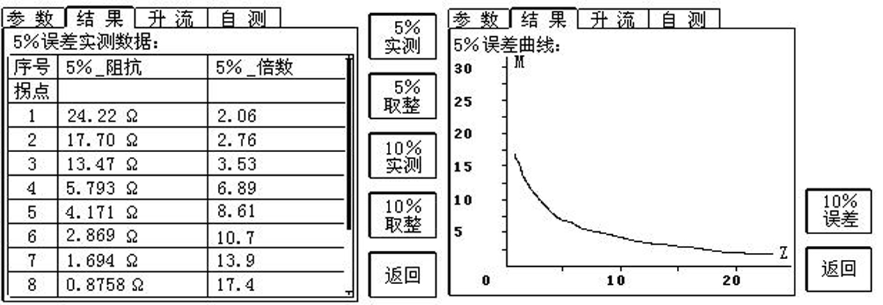
- The maximum allowable secondary impedance value under the premise of 5% (10%) error is met. Generally, the measured value is required to be far less than the calculated value (error curve). If the requirement is not met, the error may be too large and the protection may malfunction.
- Secondary load test judgment: the measured secondary load is less than the rated capacity.
- It reflects the CT load capacity, and the measured secondary load is less than the rated capacity. If the requirements are not met, the CT body may be burned or even tripping may occur.

△ Error characteristic results
Copyright © 2024 All rights Reserved.
备案号:鄂ICP备05010718号-1


