Contact: sales@haomai.net
NEWS
Company News
Commissioning Method for Generator Loss of Excitation Protection
Generator loss of excitation protection is a type of generator relay protection. When the excitation of a generator suddenly disappears or partially fades to a complete loss, the excitation current gradually decays to zero. When the power angle δ exceeds the static stability limit angle, the generator loses synchronization with the power system. At this time, the generator protection device acts on the generator outlet circuit breaker to disconnect the generator from the power grid, preventing generator damage and ensuring the stable operation of the power grid.
There are two impedance circles for the impedance criterion of the generator stator side: the asynchronous impedance circle and the static stability boundary circle, with the operating equation as follows:
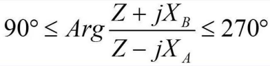
The impedance criterion can be combined with the reactive power reverse criterion: -. The figure below shows the characteristic diagrams of the static stability impedance relay and the asynchronous impedance relay, where the shaded area is the operating zone and the dashed line is the reactive power reverse operating boundary.

Static Stability Circle Asynchronous Circle
△ Variation Trajectory of Positive-Sequence Measured Impedance at Generator Terminal After Loss of Excitation

△ Variation Process of Impedance Circle After Loss of Excitation
The commissioning of generator loss of excitation protection is a key and difficult point in generator protection commissioning. The commissioning method for the impedance circle of generator loss of excitation protection is illustrated with an example as follows.
1. Partial Setting Sheet of a Generator Protection Device
|
No. |
Setting Value |
Value |
No. |
Control Word/Pressure Plate |
Value |
|
1 |
Impedance Setting ZA |
2 Ω |
4 |
Stage I Impedance Criterion |
1 (Enabled) |
|
2 |
Impedance Setting ZB |
8 Ω |
5 |
Loss of Excitation Protection |
1 (Enabled) |
|
3 |
Loss of Excitation Protection Delay |
0.1 s |
6 |
Impedance Circle Characteristic |
1 (Asynchronous Circle) |
Note: Setting the impedance circle characteristic to 1 indicates the asynchronous impedance circle, and 0 indicates the static stability circle.
2. Test Wiring
Output the voltages UA,UB,UC,UN of the Relaystar-S60 Handheld Relay Protection Test System to the generator terminal voltage terminal block of the generator protection device. Output the currents IA,IB,IC,IN of the Relaystar-S60 to the generator terminal current terminal block of the generator protection device. Connect the tripping output of the generator protection device terminal block to the input contact A and the common terminal of the Relaystar-S60.

△ Relaystar-S60 Handheld Relay Protection Test System

△ Wiring Diagram of Loss of Excitation Protection
3. Test Software and Parameter Setting
Select the Impedance Characteristic Test module.
Test item selection: Search for Impedance Boundary.
Search mode setting: Bidirectional Search (search back and forth between the operating zone and non-operating zone until the boundary is found).
Fault setting: The fault type is generally selected as ABC short circuit; the constant current mode is optional, and the short-circuit current can be set to 5A (the short-circuit current can be reduced under system load).
Time setting: The pre-fault time shall meet the PT disconnection reset requirement, generally set to 10~12s; the maximum fault time is 0.1s longer than the setting value. The test interval time is 0.5s (normal output time). The fault trigger mode is set to time trigger.
Zero-sequence compensation coefficient: No need to set the zero-sequence compensation coefficient due to the selection of three-phase short circuit.

Search center: The center can be deduced as 5Ω ((8Ω+2Ω)/2=5Ω) with an angle of ∠−90∘ according to the setting values. Set Z-Φ mode, and the software automatically converts it to R-X values.
Search radius: The radius of the asynchronous circle is deduced as 3Ω ((8Ω−2Ω)/2=3Ω) according to the setting values, and the set radius only needs to be greater than 3Ω. The search step size determines the search accuracy.
Number of search lines: Determined by the start angle, end angle and angle step size, generally set to 12 search points.
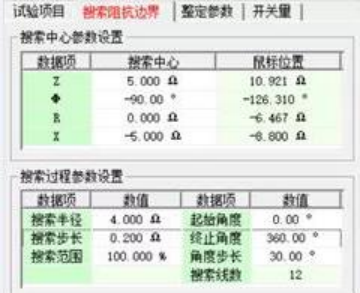
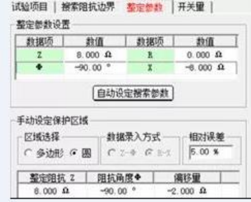
Setting parameter configuration: The setting impedance is the value on the setting sheet, which can be set to 8Ω with an angle of −90∘.
Manual setting of protection zone: Select circle characteristic for the zone. The setting impedance Z in the software is the set asynchronous impedance ZB=8Ω, and the offset is the asynchronous impedance ZA=−2Ω. For the asynchronous circle, the impedance angle is set to −90∘. Set the reactive power reverse value −Qzd to be greater than −2Ω.
4. Test Method and Results
After the test starts, the loss of excitation protection operates, and the corresponding message is displayed on the protection device. The input contact A of the Relaystar-S60 collects the operation information and marks a green dot at the corresponding search point, and the asynchronous impedance circle of the loss of excitation protection is searched out.

△ Asynchronous Circle Boundary of Loss of Excitation Protection
Thinking
What are the corresponding parameter settings and circle characteristics when the impedance circle characteristic is set to 0 (i.e., the static stability circle)?
At this time, the search center should be set to 3Ω∠−90∘, the search radius to 6Ω (greater than the static stability circle radius of 5Ω), the setting impedance to 8Ω, the offset to 2Ω, and the impedance angle to −90∘.

△ Theoretical Boundary of Static Stability Circle of Loss of Excitation Protection
24-hours hot line 400-099-8859 technical hot line: 13971234137

Copyright © 2024 All rights Reserved.
备案号:鄂ICP备05010718号-1
