Contact: sales@haomai.net
NEWS
Company News
Commissioning and Implementation Method for Transformer Inverse-Time Overexcitation Protection
When overexcitation faults occur in generators and transformers, a rise in voltage or a drop in frequency will both cause an increase in the operating magnetic flux density of the iron core. When the iron core approaches or reaches saturation, the iron core loss increases and the temperature rises; meanwhile, the increase in leakage magnetic field leads to a corresponding rise in eddy current loss. The temperature rise caused by such losses may damage the equipment insulation. The rated operating magnetic flux density of modern large generators and transformers is close to saturation, and overexcitation faults will result in more severe consequences. Therefore, all large generators and transformers shall be equipped with overexcitation protection. Overexcitation protection includes definite-time and inverse-time types, and this paper focuses on the implementation method of inverse-time overexcitation protection.
An important physical quantity — overexcitation multiple — is adopted in transformer overexcitation protection. Taking the SG T756 Digital Transformer Protection Device as an example, let the overexcitation multiple be N, which is equal to the ratio of the actual magnetic flux density B in the iron core to the rated operating magnetic flux density Bn, i.e.:
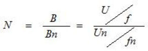
Where:N — Overexcitation multiple;
B,Bn — Actual and rated values of the magnetic flux density of the transformer iron core;
U,Un — Actual and rated voltages applied to the transformer winding;
f,fn — Actual and rated frequencies.
The transformer protection device is set with time-limited alarm and inverse-time tripping functions. The inverse-time operating characteristic adopts a seven-segment polyline, which is easy to fit the overexcitation operating characteristic curve.

The commissioning method for transformer inverse-time overexcitation protection is illustrated with an example as follows.
1. Partial Setting Sheet of a Transformer Protection Device
|
No. |
Setting Name |
Value |
No. |
Control Word/Pressure Plate |
Value |
|
01 |
Reference Voltage |
60.6 V |
01 |
Inverse-Time Overexcitation Alarm |
1 (Enabled) |
|
02 |
Inverse-Time Overexcitation Stage I Multiple |
1.35 |
02 |
Inverse-Time Overexcitation Tripping |
1 (Enabled) |
|
03 |
Inverse-Time Overexcitation Stage I Time |
0.5 s |
— |
— |
— |
|
04 |
Inverse-Time Overexcitation Stage II Multiple |
1.28 |
— |
— |
— |
|
05 |
Inverse-Time Overexcitation Stage II Time |
2 s |
— |
— |
— |
|
06 |
Inverse-Time Overexcitation Stage III Multiple |
1.20 |
— |
— |
— |
|
07 |
Inverse-Time Overexcitation Stage III Time |
5 s |
— |
— |
— |
2. Test Wiring
Output the voltages UA,UB,UC,UN of the Relaystar-S60 Handheld Relay Protection Test System to the terminal block of the generator terminal voltage of the transformer protection device. Connect the tripping output of the generator protection device terminal block to the input contact A and the common terminal of the Relaystar-S60.

△ Relaystar-S60 Handheld Relay Protection Test System

△ Wiring Diagram of Inverse-Time Overexcitation Protection
3. Test Software and Parameter Setting
Select the state sequence module and set State 1 (normal state): set the amplitude of the three-phase rated voltage for Ua,Ub,Uc, the three-phase positive sequence angle, the frequency to 50Hz, and the trigger condition to key trigger.

Set State 2 (fault state) to simulate a Stage I fault: set the amplitude of phase A voltage (fault phase) to: 60.6 V×1.35=81.81 V; set the three-phase positive sequence angle, the frequency to 50Hz; set the trigger condition (time greater than the setting value of 0.5s) to 0.6s.

4. Test Method and Results
Start the test and the system enters the normal State 1. After the alarm signal of the protection device is reset, press the Tab key to switch to the fault State 2. When the inverse-time overexcitation protection operates, the relay of the Relaystar-S60 emits a tripping beep, and the screen of the transformer protection device displays the corresponding message: "Inverse-Time Overexcitation Stage I Operated". The input contact A of the Relaystar-S60 collects the operating time of 0.524s, indicating that the test is completed with correct operation and the protection function is normal.
Complete the tests for Stage II and Stage III of inverse-time overexcitation protection with reference to the above method and steps.
24-hours hot line 400-099-8859 technical hot line: 13971234137

Copyright © 2024 All rights Reserved.
备案号:鄂ICP备05010718号-1
