Contact: sales@haomai.net
NEWS
Company News
Commissioning Method for Differential Protection of Voltage Regulating and Compensation Transformer
UHV substations usually adopt 1000kV autotransformers, and a separate voltage regulating and compensation transformer can be installed outside the main transformer. The voltage regulating transformer and compensation transformer are three-phase split-phase transformers. During operation, due to the differences in CT transformation ratios, gear positions and current magnitudes on each side, digital compensation is required to eliminate the current magnitude differences. To prevent the insufficient sensitivity of the main transformer protection to the interturn faults of the voltage regulating and compensation transformer, a dedicated differential protection for the voltage regulating and compensation transformer must be configured.
1. Principle Introduction
The longitudinal differential protection of the voltage regulating transformer refers to the differential current formed by the bushing CTs on each side of the transformer, which can reflect various fault types on each side of the voltage regulating transformer. Below, we take the Relaystar-7000 Integrated Digital Relay Protection Test System and SG T756 Digital Transformer Protection Device as examples to introduce the commissioning method for differential protection.

△ Relaystar-7000 Integrated Digital Relay Protection Test System
1.1 Secondary Rated Current on Each Side of the Voltage Regulating Transformer
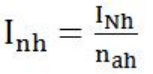
Rated current of the angular side (high-voltage side) of the voltage regulating transformer:
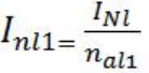
Rated current of the common winding on the star side (low-voltage 1 side) of the voltage regulating transformer:
Rated current of the compensation side on the star side (low-voltage 2 side) of the voltage regulating transformer:
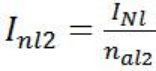
Where: CT is fully Y-connected;INh,INl — Primary rated current of the high and low voltage sides of the voltage regulating transformer;nah,nal1,nal2 — CT transformation ratios of the high and low voltage sides of the voltage regulating transformer.
Due to the differences in voltage levels and CT transformation ratios on each side, the current on each side must be converted when calculating the differential current, and the current on each side of the protection device is converted to the high-voltage side.
1.2 Calculation Method of Balance Coefficient on Each Side of the Voltage Regulating Transformer
Balance coefficient of the rated current on the angular side (high-voltage side) of the voltage regulating transformer:Kh=1
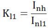
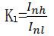
Balance coefficient of the rated current of the common winding on the star side (low-voltage 1 side) of the voltage regulating transformer:
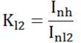
Balance coefficient of the rated current of the compensation side on the star side (low-voltage 2 side) of the voltage regulating transformer:
Since the voltage regulating transformer is a Y/Y split-phase transformer, there is no star-to-delta (Y→△) conversion issue in differential current calculation, and it is a phase differential protection.
1.3 Current on Each Side of the Voltage Regulating Transformer
![]()
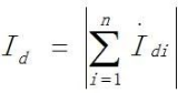
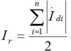
Where I is the measured secondary vector value of the current on each side, and Idi is the converted vector value of the current on each side.
1.4 Differential Current
1.5 Restraining Current
1.6 Steady-State Ratio Differential Protection


Id - Differential current, Ir - Restraining current, Iop.min - Minimum operating current (0.4Ie in the setting sheet), Is1 - First restraining current inflection point (0.8Ie), Is2 - Second restraining current inflection point (3Ie is taken); K1=0.5, K2=0.7, Ie - Rated current of the reference side.
1.7 Differential Current Calculation of the Compensation Transformer
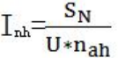
Primary rated current of the star side (high-voltage side) of the compensation transformer:
Rated current of the angular side (low-voltage side) of the compensation transformer:
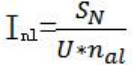
Where In is the rated current, SN is the rated capacity, U is the rated phase voltage, and n is the transformation ratio of each side.
1.8 Balance Coefficient of the Compensation Transformer
Balance coefficient of the rated voltage on the star side (high-voltage side) of the compensation transformer:Kh=1
Balance coefficient of the rated voltage on the angular side (low-voltage side) of the compensation transformer:
2. Test Preparation
- Calculate the rated current of the delta side (high-voltage side) and star side (low-voltage side):INh=220.72/1000=0.22 AINl=1660.65/2500=0.66 ABalance coefficients: Kh=1, Kl=0.22/0.66=0.33
- Verify the slope:Select any two points on the slope polyline of the K1 segment to deduce the applied current. For slope verification, take Ie and 2Ie, where = and Ir2=Ie. Calculate Id according to the formula and deduce the high and low voltage side currents to be applied.
Take Ir1=2Ie, calculate:Id=0.4Ie+(2Ie−0.8Ie)×0.5=IeCalculate the current on each side from the formula:Ih1=2.5Kh=0.56 A, Il1=1.5Kl=0.99 A
When Ir2=Ie, Calculate the currents similarly:Ih2=1.25Kh, Il2=0.75Kl
- Test Wiring

The high-voltage side current is connected from IA, IB, IC, IN of the Relaystar-7000A to the CT winding on the high-voltage side of the protection device, and the low-voltage side current is connected from Ia, Ib, Ic, In of the tester to the winding on the low-voltage side of the protection device. The input contact A is connected to the tripping output of the protection device.
4. Test Software and Parameter Setting
Select the AC Test Module, set all six channels of voltage to zero, set the three-phase current on the high-voltage side to 0.56A with positive phase sequence and a step size of zero. To ensure the differential protection does not operate reliably in the initial state, set the three-phase current on the low-voltage side to 1.20A (at this time, <, >, in the restraining zone) with positive phase sequence, a step size of 0.01A, and the variation mode set to manual test.

5. Test Operation and Results
Run the test after completing the parameter setting on the software interface, select step-down decrement until the protection device operates. Observe the ratio differential action in the protection device message, as well as the operating current and operating time. Operate with Ir2=Ie using the same method. At this time, two sets of differential current and restraining current values are obtained through the differential current and restraining current calculation formulas:Id1=0.385 A, Ir1=0.753 AId2=0.21 A, Ir2=0.41 A
According to the ratio differential slope formula:
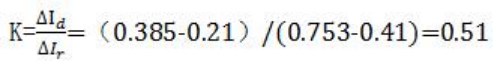
That is, the error of the ratio restraining coefficient is verified as:0.50.51−0.5=2%which meets the error requirements.
24-hours hot line 400-099-8859 technical hot line: 13971234137

Copyright © 2024 All rights Reserved.
备案号:鄂ICP备05010718号-1
