Contact: sales@haomai.net
NEWS
Company News
Principle and Method for Calibration of Main Transformer Differential Protection
Protection Device: NR Electric PCS-9671D Transformer Differential Protection Device
Test Equipment: Relaystar-7000 Digital-Analog Integrated Relay Protection Tester
The PCS-9671D Transformer Differential Protection Device is applicable to two-winding or three-winding transformers with various connection modes at voltage levels of 110kV and below, meeting the differential protection requirements for four sides. This article focuses on the differential protection calibration of Yd11-connected two-winding transformers without bridge sides using the Relaystar-7000 Digital-Analog Integrated Relay Protection Tester, including differential current balance calibration, differential instantaneous trip calibration, and percentage differential calibration. The Relaystar-7000 supports simultaneous output of power amplifier signals with IEC61850-9-2/9-1 or FT3 signals, enabling tests under complex on-site conditions.

△ Typical Application Configuration of Transformer Differential Protection Device
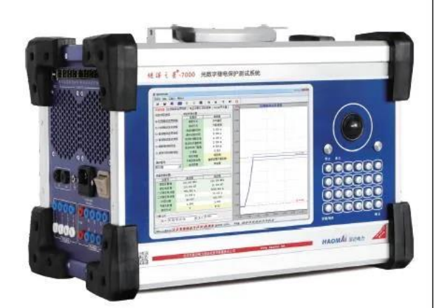
△ Relaystar-7000 Digital-Analog Integrated Relay Protection Tester
I Differential Current Balance Calibration
The Relaystar-7000 is used to simulate the load consistent with the operating state to verify the correctness of the wiring and setting values of the main transformer differential protection current circuit. The calibration can be conducted in three-phase mode or single-phase mode.
1 Three-Phase Calibration
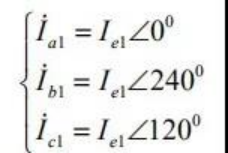
According to the transformer connection mode, the Relaystar-7000 provides 6 channels of current to simulate normal load current for the three-phase differential current balance test on the high-voltage side and low-voltage side.During the test, the phase setting is based on the phase A of the high-voltage side (0° for phase A, 240° for phase B, 120° for phase C), and the three-phase current on each side is connected with positive polarity.
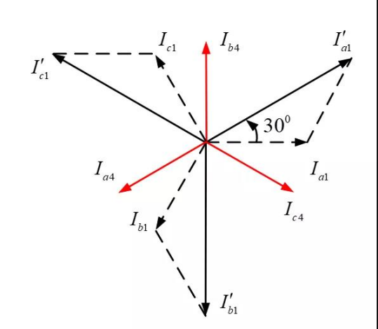
△ Phasor Diagram
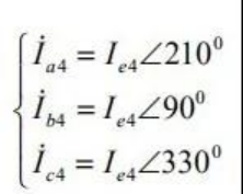
Apply three-phase currents with the magnitude of the secondary equivalent rated current of the local side to the high-voltage and low-voltage sides respectively, and the phase relationship is determined by the clock number of the connection mode of the local side. In this example, the clock number of the low-voltage side connection mode is 11, so the phase angles of the applied three-phase currents are set to 210°, 90°, and 330° respectively (i.e., the high-voltage side current leads the corresponding phase current of the low-voltage side by 150°).
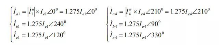
Three-phase current applied to the high-voltage side:
Three-phase current applied to the low-voltage side:
When currents are applied to the high-voltage and low-voltage sides respectively, the secondary currents of the two sides after phase and amplitude correction are as follows:
High-voltage side:
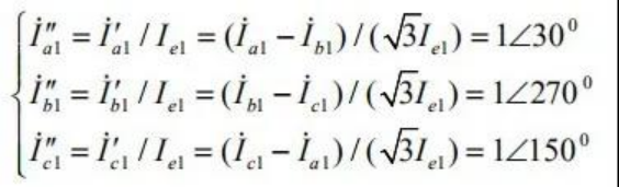
Low-voltage side:
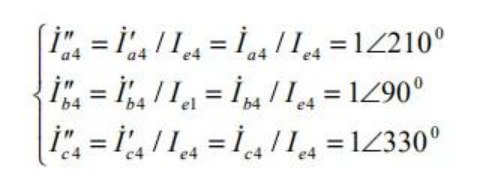
It can be concluded that the differential currents of phases A, B and C are all 0, and the differential current can be viewed on the device.
2 Single-Phase Calibration
If the relay protection tester can only provide 3 channels of current, the differential current balance calibration can be conducted by applying single-phase current to the high-voltage side and two-phase current to the low-voltage side.
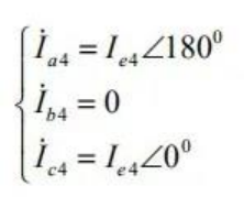
The magnitude and phase relationship of the current applied to each side can be determined according to the transformer connection mode and current adjustment method. In this example, the clock number of the low-voltage side connection mode is 11. During calibration, apply a single-phase current with the magnitude of the secondary equivalent rated current of the local side to the high-voltage side (e.g., 0° for phase A), and apply a reverse in-phase current and a forward leading-phase current with the same magnitude to the low-voltage side (e.g., 180° for phase A, 0° for phase C).
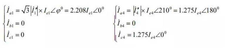
Three-phase current applied to the high-voltage side:
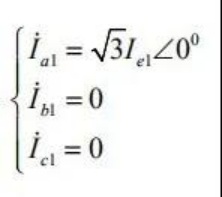
Three-phase current applied to the low-voltage side:
When currents are applied to the high-voltage and low-voltage sides respectively, the secondary currents of the two sides after phase and amplitude correction are as follows:
High-voltage side:
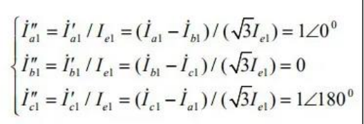
Low-voltage side:
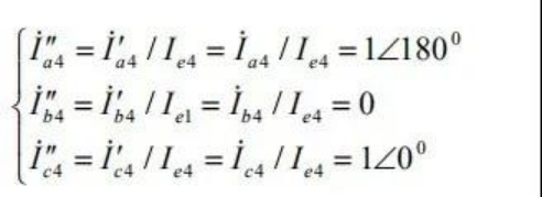
It can be concluded that the differential currents of phases A, B and C are all 0, and the differential current can be viewed on the device.
II Differential Instantaneous Trip Calibration
The calibration can be conducted on the high-voltage side or low-voltage side, and only single-phase current is usually applied during the test. Before calibration, close the hard press plate, soft press plate of differential protection and the control word for differential instantaneous trip enable.
1 Calibration on the High-Voltage Side
Apply single-phase current (e.g., phase A) to the high-voltage side with no current applied to the low-voltage side. The percentage differential protection shall operate reliably when m=1.05, and not operate reliably when m=0.95.
2 Calibration on the Low-Voltage Side
Apply single-phase current (e.g., phase A) to the low-voltage side with no current applied to the high-voltage side. The percentage differential protection shall operate reliably when m=1.05, and not operate reliably when m=0.95.
III Percentage Differential Characteristic Calibration
The percentage differential characteristic curve is a multi-segment polyline, and only two points need to be calibrated for each polyline segment. For example, to calibrate the second polyline segment in the figure below, two points with braking currents of Ir=Ie1 and Ir=Ie2 can be selected. The calibration can be conducted in three-phase mode or single-phase mode.

1 Calibration Principle
Balance point and test point: The balance point refers to the point where the differential current is 0, and the test point refers to the point on the braking curve.For example, given a braking current Ir=1 and a corresponding differential current Id=1, the high and low-voltage side currents corresponding to the balance point can be calculated as:I1=I2=Ir+0.5Id=Ir=1
At this time, if the high-voltage side current is fixed and the low-voltage side current is reduced, the differential current increases and the braking current decreases, transitioning from the balance point to the test point as shown in the figure above. Since it is cumbersome to find the test point, the common method is to specify the braking current first, then find the corresponding test point.
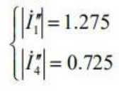
For example, take the braking current Ir=1, and calculate the differential current Id=0.55 corresponding to this braking current according to the percentage differential characteristic curve. Then, from the calculation formulas of differential current and braking current:
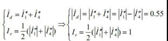
The high and low-voltage side currents corresponding to the test point can be calculated as:
2 Calibration Methods
Method 1: Transition from Balance Point to Test Point
Select the first braking current, first apply the balance current (corresponding to the balance point in the figure above).
Fix the current applied to the high-voltage side, and gradually reduce the current applied to the low-voltage side until the percentage differential protection operates. The point calculated from the applied currents of the two sides at this time should be close to the test point in the figure above.
Select the second braking current and verify it using the same method.
Method 2: Direct Calibration Method
Assume the braking curve is correct by default.
Select the first test point, and directly apply the currents corresponding to the test point to the high and low-voltage sides.
Slightly increase the low-voltage side current: the percentage differential protection does not operate; slightly reduce the low-voltage side current: the percentage differential protection operates.
Select the second test point and verify it using the same method.
3 Three-Phase Calibration
The calibration method is similar to the three-phase calibration for differential current balance, with only the magnitude of the applied current being different.Taking the first braking current Ir=1 as an example:
First apply the balance current:
Then gradually reduce the magnitude of the current applied to the low-voltage side until the percentage differential protection operates.
Verify the second braking current using the same method.
4 Single-Phase Calibration
The calibration method is similar to the single-phase calibration for differential current balance, with only the magnitude of the applied current being different.Taking the first braking current Ir=1 as an example:
First apply the balance current:
Then gradually reduce the magnitude of the current applied to the low-voltage side until the percentage differential protection operates.
Verify the second braking current using the same method.
24-hours hot line 400-099-8859 technical hot line: 13971234137

Copyright © 2024 All rights Reserved.
备案号:鄂ICP备05010718号-1
