Contact: sales@haomai.net
NEWS
Company News
Secondary Circuit Test: Relay Protection Phasor Check Method VS Voltage Injection Method
According to the primary wiring diagram of a power plant, the station service power is divided into Section A and Section B. For a systematic inspection of the voltage circuit, the traditional voltage injection method and the relay protection phasor check method were adopted respectively. The following prerequisites must be met before conducting tests with either method:
- The enclosed busbars between the high-voltage station transformer and the 6kV section, as well as between the station service standby transformer and the 6kV section, are not connected. If already installed, the flexible connections between them must be disconnected, enclosures set up at the joints, warning lines drawn, and dedicated personnel posted if necessary.
- The 6kV section small busbars are installed, passed the withstand voltage test, cleaned thoroughly, and hermetically sealed in good condition.
- The internal and external circuit wires of each section have been calibrated and verified to be accurate.
- The internal and external circuit wires of each section have been tested for insulation and qualified.
- Push the standby incoming line PT trolley, working incoming line PT trolley and busbar PT trolley into the bays to the working position; open all bay switches and voltage air switches in the sections. Evacuate unrelated personnel from the high-voltage section, draw warning lines around the test area, and post warning signs.


△ Primary Wiring Diagram
I Secondary Circuit Voltage Injection Test
The traditional method leverages the PT operating principle and adopts the mutual inductance method—injecting voltage into the PT secondary circuit, which is induced to the primary circuit through electromagnetic induction, achieving a comprehensive inspection of the voltage secondary circuit.
Voltage boosting is realized via the standby or working incoming line PT trolleys of Station Service Power Sections A and B to simulate the normal operation of high-voltage station service power and inspect the voltage secondary circuit. Due to the adoption of the PT mutual inductance method, the primary busbar is at the normal operating voltage, so the primary phase checking of high-voltage station service power Sections A and B can be completed on the secondary side of the busbar PT.

△ Commissioning Process
Inject a voltage of 57.7V into phases A, B and C respectively (taking a secondary rated voltage of 100V as an example) on the secondary side of the standby incoming line PT of Station Service Power Sections A and B using a relay protection tester.
Check the correctness of the voltage phase sequence and phasor display at the busbar PT bays of Sections A and B with a phase sequence meter and a multimeter.
After confirmation, conduct phase checking on the secondary side of the busbar PT (complete primary phase checking) with a multimeter: measure the voltage of Phase A of Section A against Phases A, B, C of Section B, Phase B of Section A against Phases B, C of Section B, and Phase C of Section A against Phase C of Section B respectively; check if the voltage difference is within the allowable range and judge if the phase-to-phase voltage difference meets the phase checking standard.
Repeat the above operations for voltage injection on other working incoming line sections.
II Relay Protection Phasor Integrated Check Method
The relay protection phasor check device injects constant current/constant voltage into both ends of the CT/PT primary circuit of the substation main wiring. The current/voltage is transformed by the transformers and injected into the secondary circuit, from which the protection device acquires real sampling values. Cooperated with the YD-300 Wireless Telemetry Voltage-Current Phase Indicator, it realizes wireless secondary phase checking to inspect differential polarity, voltage and current synchronization, etc.
The HTA-3300 Three-phase Digital Intelligent High-current Source and HTV-6000 Three-phase Digital Intelligent High-voltage Source are placed near the CT and PT of the main wiring respectively to shorten the wiring length, with a certain distance between the two devices. During the test, the output voltage and current of the two devices must have the same frequency and synchronous phase (any phase relationship can be set). The two devices achieve frequency and phase synchronization via wireless communication and are controlled by a single controller—the YD-300 Wireless Telemetry Voltage-Current Phase Indicator—facilitating the injection of any specified voltage and current for phasor testing.

△ HTV-6000 Three-phase Digital Intelligent High-voltage Source
Place the voltage source on the primary cable incoming side of the PT of Sections A and B; at this time, the 6kV panel top small busbar is energized. Inspect the voltage circuit of the 6kV outgoing cabinet with the YD-300 in sequence, and complete the secondary phase checking of the busbar voltage of the two sections through wireless communication between two YD-300 devices.
△ Voltage Circuit Inspection
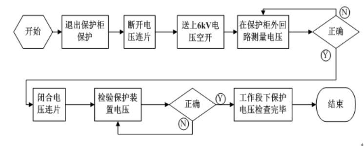
Inspect the fault recording voltage and fast switching voltage at the busbar bays:
Disconnect the protection cabinet from its protected equipment (disconnect the external circuit protection outlet wiring or cut off the equipment operating power), and open the voltage connecting pieces in the panel cabinet.
Measure the voltage at the external circuit of the protection cabinet; close the voltage connecting pieces after confirmation, and inspect the voltage normalcy from the protection device to prevent damage to the plug-ins in the protection panel cabinet caused by fault voltage.
After confirming the normal voltage at the busbar PT bays, inspect the working power incoming line bays:
Close the voltage air switch and check the correctness of the secondary voltage phase sequence and phasor on the protection device or measuring instrument.
After the inspection of the working power incoming line bay and confirmation of accurate voltage, open the voltage air switch of this bay.
Close the voltage air switch of the next bay and repeat the above inspection method; open the voltage air switch after confirmation. Cut off the load of one device after completing the inspection of each bay to prevent the instrument from shutting down due to overload during the test.
Inspect Section B immediately after Section A until the entire section of panel cabinets is inspected.
Inspect the unit transformer protection voltage and fast switching protection voltage at the working incoming line bays:
First, disconnect the protection cabinet from its protected equipment (disconnect the external circuit protection outlet wiring, cut off the equipment operating power or exit the protection on the panel) to prevent circuit breaker operation and equipment damage caused by the test.
Open the voltage connecting pieces in the panel cabinet and close the relevant voltage air switches of the 6kV section working incoming line.
Measure the voltage at the external circuit of the protection cabinet first; close the voltage connecting pieces after confirmation, inspect the voltage normalcy from the protection device and keep records to prevent damage to the plug-ins in the protection panel cabinet caused by fault voltage.
During the process, each test personnel shall perform their duties, monitor the operation of instruments and equipment at all times, and promptly inform the operator of the received information.
This test completed the inspection of voltage and current circuits. Considering the time urgency of reverse power transmission, the set of equipment was used for primary power transmission simulation to complete the on-load test and verify the correctness of the 6kV busbar differential protection.
Comparison with the Traditional Voltage Injection Method
- The relay protection phasor check device injects signals from the source of primary equipment, enabling a comprehensive inspection of live circuits.
- Restricted by equipment capacity, the traditional method may cause equipment damage due to overload, and cannot conduct multi-bay inspection for a long time or phase checking between dual power supply points. The relay protection phasor check device can realize boosting of the entire busbar, simplifying the workload.
- Cooperated with the YD-300 Wireless Telemetry Voltage-Current Phase Indicator, the device can inspect phase and amplitude without distance limitation, solving the problem of phase checking distance between the PT voltages of the station service power sections.
- The relay protection phasor check device features safer operation, equipped with an emergency stop button and a remotely controlled voltage output switch.
24-hours hot line 400-099-8859 technical hot line: 13971234137

Copyright © 2024 All rights Reserved.
备案号:鄂ICP备05010718号-1
