Contact: sales@haomai.net
NEWS
Company News
Commissioning Method for the Percentage Restraint Coefficient of Busbar Protection Total Differential and Partial Differential
The differential loop of busbar protection includes the busbar total differential loop and the partial differential loop of each busbar section. The busbar total differential refers to the differential loop formed by the currents of all branches except the bus tie switch and the sectional switch. The partial differential of a certain busbar section refers to the differential loop formed by the currents of all branches connected to this busbar section (including the bus tie and sectional switches). The busbar total differential percentage restraint is used to distinguish internal and external busbar faults, while the partial differential percentage restraint is used to select the faulty busbar.
According to the settings of the CYG Sunry BP-2C Busbar Protection Device:
When both the "Split Operation Press Plate" of the bus tie switch and the bus tie TWJ (Trip Position Relay) input are 0, and the HWJ (Close Position Relay) input is 1, the total differential percentage restraint coefficient is the same as the partial differential percentage restraint coefficient, both adopting the high value of the percentage restraint coefficient.
When both the "Split Operation Press Plate" of the bus tie switch and the TWJ input are 1, and the HWJ input is 0, the total differential percentage restraint element automatically switches to the low value of the percentage restraint coefficient, while the partial differential percentage restraint coefficient remains unchanged and still adopts the high value.
The high value (0.5) and low value (0.3) are solidified internally and do not require setting. In busbar protection, the total differential is responsible for fault judgment, and the partial differential is responsible for busbar selection. For the double-busbar single-section wiring diagram, the dotted terminals of the CT polarities of each bus tie are shown in the figure, and the dotted terminals of the CT polarities of each branch are on the busbar side.

△ Primary System Schematic Diagram
1 Commissioning Method for the High Value (0.5) of the Total Differential Percentage Restraint Coefficient
Select Branch 2 and Branch 3 to be connected to Busbar II A, and Branch 4 to be connected to Busbar I. Keep Bus Tie Switch 1 in the closed position.
Set the SV receiving soft press plates of Branch 2, Branch 3 and Branch 4 to "1", and set the other SV soft press plates to "0". Set the Bus Tie 1 Interconnection Soft Press Plate to "1" and the Split Operation Soft Press Plate to "0".
After configuring the SV of each bay, map the test IA phase current to the IA phase current of Branch 2, the IB phase current of the Relaystar-S60 Handheld Relay Protection Tester to the IA phase current of Branch 3, and the IC phase current to the IA phase current of Branch 4.

△ Relaystar-S60 Handheld Relay Protection Tester

△ Total Differential Commissioning Wiring Diagram
Set the test parameters as shown in the table below (taking the bus differential current setting value of 0.3A as an example for this test):
|
Voltage/Current Value |
Variable |
Step Size |
|
IA/A: 0.5∠0° |
- |
- |
|
IB/A: 0.5∠180° |
- |
- |
|
IC/A: 0∠0° |
√ |
0.1 |
△ Initial Value Settings for Total Differential High-value Commissioning
Click Start to run the test. At this time, the protection device does not operate. Continuously increase the IC value while observing the indicator lights on the protection device panel until the "Bus Differential Operation" indicator light turns on.
Record the IC current value at this time, which should be 0.5A.
Calculate the high value of the total differential percentage restraint coefficient using the following method:
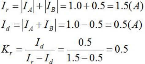
The calculated high value K of the total differential is 0.5, which is consistent with the target value of 0.5, indicating that the test is qualified.
2 Commissioning Method for the Low Value (0.3) of the Total Differential Percentage Restraint Coefficient
Select Branch 2 and Branch 3 to be connected to Busbar II A, and Branch 4 to be connected to Busbar I. Keep Bus Tie Switch 1 in the open position.
Set the SV receiving soft press plates of Branch 2, Branch 3 and Branch 4 to "1", and set the other SV soft press plates to "0". Set the Bus Tie 1 Interconnection Soft Press Plate to "0" and the Split Operation Soft Press Plate to "1".
After configuring the SV of each bay, map the test IA phase current to the IA phase current of Branch 2, the IB phase current of the Relaystar-S60 to the IA phase current of Branch 3, and the IC phase current to the IA phase current of Branch 4.
Set the test parameters as shown in the table below (taking the bus differential current setting value of 0.3A as an example for this test):
|
Voltage/Current Value |
Variable |
Step Size |
|
IA/A: 0.5∠0° |
- |
- |
|
IB/A: 0.5∠180° |
- |
- |
|
IC/A: 0∠0° |
√ |
0.1 |
△ Initial Value Settings for Total Differential Low-value Commissioning
Click Start to run the test. At this time, the protection device does not operate. Continuously increase the IC value while observing the indicator lights on the protection device panel until the "Bus Differential Operation" indicator light turns on.
Record the IC current value at this time, which should be 0.3A.
Calculate the low value of the total differential percentage restraint coefficient using the following method:
The calculated low value K of the total differential is 0.3, which is consistent with the target value of 0.3, indicating that the test is qualified.
3 Commissioning Method for the Partial Differential Percentage Restraint Coefficient (0.5)
Select Branch 2 and Branch 3 to be connected to Busbar II A. Keep Bus Tie Switch 1 in the open position.
Set the SV receiving soft press plates of Branch 2 and Branch 3 to "1", and set the other SV soft press plates to "0". Set the Bus Tie 1 Interconnection Soft Press Plate to "0" and the Split Operation Soft Press Plate to "1".
After configuring the SV of each bay, map the test IA phase current to the IA phase current of Branch 2, and the IB phase current of the Relaystar-S60 to the IA phase current of Branch 3.

△ Partial Differential Commissioning Wiring Diagram
Set the test parameters as shown in the table below (taking the bus differential current setting value of 0.3A as an example for this test):
|
Voltage/Current Value |
Variable |
Step Size |
|
IA/A: 1.0∠0° |
- |
- |
|
IB/A: 1.0∠180° |
√ |
0.1 |
|
IC/A: 0∠0° |
- |
- |
△ Initial Value Settings for Partial Differential Commissioning
Click Start to run the test. At this time, the protection device does not operate. Continuously decrease the IB value while observing the indicator lights on the protection device panel until the "Bus Differential Operation" indicator light turns on.
Record the IB current value at this time, which should be 0.5A.
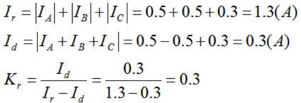
Calculate the partial differential percentage restraint coefficient using the following method:
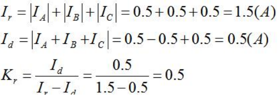
The calculated K value of the partial differential is 0.5, which is consistent with the target value of 0.5, indicating that the test is qualified.
24-hours hot line 400-099-8859 technical hot line: 13971234137

Copyright © 2024 All rights Reserved.
备案号:鄂ICP备05010718号-1
