Contact: sales@haomai.net
NEWS
Company News
Verification Method for High and Low Values of Line Pilot Differential Protection
Test Device: NR Electric RCS-931 Line Protection Device
Testing Instrument: Relaystar-Z30 Handheld Relay Protection Tester
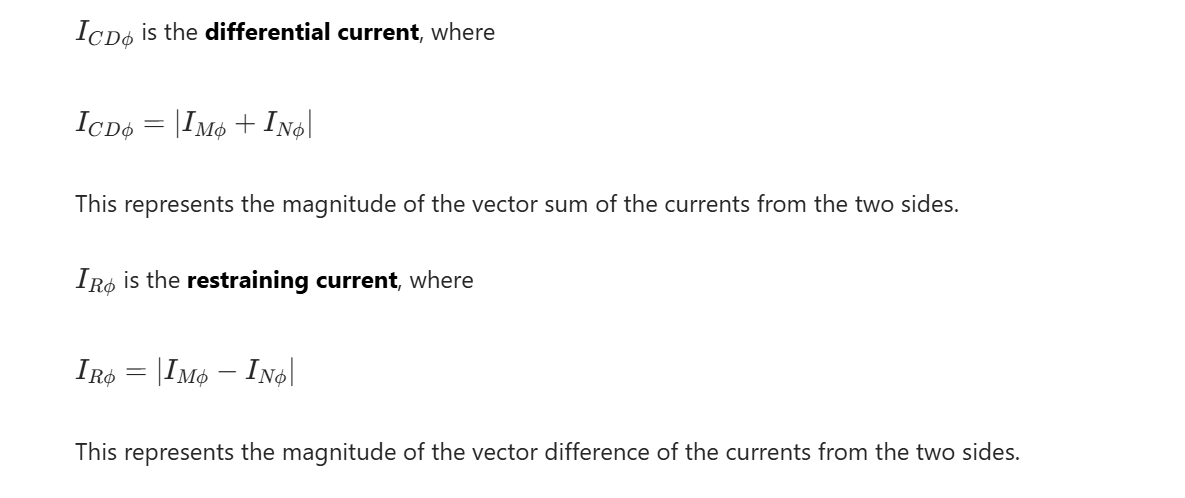
Line pilot differential protection serves as the main protection for transmission lines and is frequently involved in commissioning work. Conventional verification methods typically apply 1.05 times or 0.95 times the setting value directly, but they cannot accurately verify the operation behaviors of pilot differential Stage I (high setting value) and pilot differential Stage II (low setting value). The RCS-931 line protection device developed by NR Electric adopts a steady-state phase differential relay for line pilot differential protection, and its operating equation is as follows:
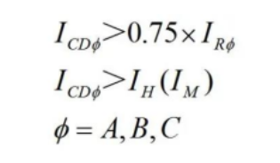
The steady-state Stage I differential relay adopts a high setting value IH, where IH is the maximum value among the differential current high setting value, 4 times the measured capacitive current, and 4UN/XC1.The operating time of differential protection Stage I is 10∼25ms.
The steady-state Stage II differential relay adopts a high setting value IH, where IH is the maximum value among the differential current high setting value, 1.5 times the measured capacitive current, and 1.5UN/XC1.The operating time of differential protection Stage II is 40∼60ms.
The measured capacitive current is obtained from the uncompensated differential current during normal operation.UN is the rated voltage, and XC1 is the positive-sequence capacitive reactance setting value.For ease of commissioning, XC1 is set to a large value here to ensure that the capacitive current is small and does not affect the commissioning.
This paper introduces how to use the Relaystar-Z30 Handheld Relay Protection Tester to conduct the high and low value test of the pilot differential protection for the RCS-931 line protection device.
I Protection-related Settings
- Protection Setting Value and Control Word Configuration
|
Serial Number |
Setting Name |
Value |
Setting Name |
Value |
|
01 |
Differential Variation Start Current Setting |
0.1A |
Pilot Differential Protection Enable |
1 |
|
02 |
Zero-sequence Start Current Setting |
0.2A |
CT Breakage Blocking Differential Protection |
0 |
|
03 |
Differential Operating Current High Setting Value |
2A |
Communication Internal Clock |
1 |
|
04 |
Differential Operating Current Low Setting Value |
1A |
- |
- |
|
05 |
Local Side Identification Code |
1 |
- |
- |
|
06 |
Remote Side Identification Code |
1 |
- |
- |
- Protection Press Plate Configuration
In the "Press Plate Settings", set the "Differential Protection" soft press plate to "1". On the protection panel, put into service the "Differential Protection" function hard press plate and the "Maintenance" function hard press plate, disconnect the "Trip Output" hard press plate, and check that the optical fiber channel of the protection device is in the loopback state.
II Test Wiring
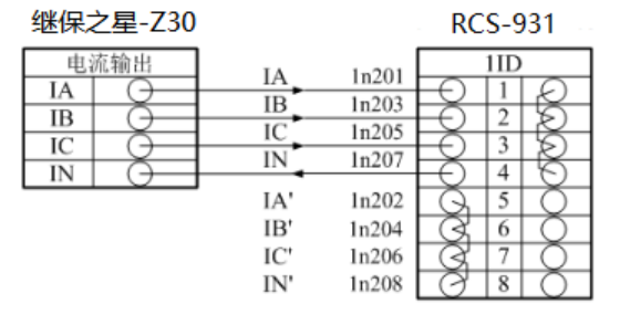
△ RCS-931 Pilot Differential Protection Wiring Diagram
Connect the current output terminals "Ia", "Ib", "Ic" of the Relaystar-Z30 to the AC current "IA", "IB", "IC" (polarity terminals) of the protection device respectively. Then short-circuit the AC current "IA'", "IB'", "IC'", "IN'" (non-polarity terminals) of the protection device, and connect the "IN" (zero-sequence current polarity terminal) back to the current output terminal "In" of the Relaystar-Z30. Connect the input contact "A" of the Relaystar-Z30 to the phase-separated trip output contact "Trip A" of the protection device, and connect the "+KM" terminal of the Relaystar-Z30 to the common terminal of the protection device.
III Verification of High and Low Values of Pilot Differential Protection
The Relaystar-Z30 has a built-in rich set of test modules, which can realize switching between analog quantity mode and digital simulation mode, meeting the testing requirements of most scenarios.

△ Relaystar-Z30 Software Main Interface
1. Verify the Operation of Differential Protection High Setting Value (Pilot Differential Stage I)
- Verify Reliable Non-operation of Differential Protection at 0.95 Times the Setting Value
Simulate a three-phase short-circuit fault. Based on the pilot differential high setting value of 2.0A, the calculated differential current test value is 2×0.5×0.95=0.95A.
① In the "State Sequence" menu, add two states: pre-fault and fault.
Pre-fault state: UA=UB=UC=57.734V, IA=IB=IC=0A, both voltage and current are in positive sequence; trigger mode: time trigger, 10s.

△ Normal State Parameter Settings
Fault state: UA=UB=UC=57.734V, IA=IB=IC=0.95A, both voltage and current are in positive sequence; trigger mode: time trigger, 40ms. Note that if the time setting is too long, the pilot differential Stage II will operate. To clearly distinguish the operation of Stage I and Stage II, the time setting here should satisfy the non-operation condition of Stage I while not meeting the operation condition of Stage II.

△ Fault State Parameter Settings
② Apply the test quantities. After completing the settings, click Run. The Relaystar-Z30 outputs according to the normal state settings for 10s. After 10s, the device automatically switches to the next state and outputs according to the fault state settings for 40ms.
③ Test Result: The protection device does not operate, and the Relaystar-Z30 does not collect a trip signal.
- Verify Reliable Operation of Differential Protection at 1.05 Times the Setting Value
Simulate a three-phase short-circuit fault. Based on the differential high setting value of 2.0A, the calculated differential current test value is 2.0×1.05×0.5=1.05A.
① In the "State Sequence" menu, add two states: pre-fault and fault. The settings for State 1 refer to the normal state parameter settings in the above figure.
State 2 settings refer to the figure below: UA=UB=UC=57.734V, IA=IB=IC=1.05A, both voltage and current are in positive sequence; trigger mode: time trigger, 40ms.

△ Fault State Parameter Settings
② Apply the test quantities. After completing the settings, click Run. The Relaystar-Z30 outputs according to the normal state settings for 10s. After 10s, the device automatically switches to the next state and outputs according to the fault state settings for 40ms.
③ Test Result: The protection device operates with the trip indicator light on. The Relaystar-Z30 receives the trip signal sent by the protection device, and the input A port of the switch quantity measures an operation time of 22ms.
2. Verify the Operation of Differential Protection Low Setting Value (Pilot Differential Stage II)
- Verify Reliable Non-operation of Differential Protection at 0.95 Times the Setting Value
Simulate a phase A ground fault. Based on the pilot differential low setting value of 1.0A, the calculated differential current test value is 1×0.5×0.95=0.475A.
① In the "State Sequence" menu, add two states: pre-fault and fault. The settings for State 1 refer to the normal state parameter settings in the above figure.
State 2 settings refer to the figure below: UA=UB=UC=57.734V, IA=IB=IC=0.475A, both voltage and current are in positive sequence; trigger mode: time trigger, 100ms.

△ Fault State Parameter Settings
② Apply the test quantities. After completing the settings, click Run. The Relaystar-Z30 outputs according to the normal state settings for 10s. After 10s, the device automatically switches to the next state and outputs according to the fault state settings for 100ms.
③ Test Result: The protection device does not operate, and the Relaystar-Z30 does not collect a trip signal.
Verify Reliable Operation of Differential Protection at 1.05 Times the Setting ValueSimulate a phase A ground fault. Based on the differential low setting value of 1.0A, the calculated differential current test value is 1.0×1.05×0.5=0.525A.
① In the "State Sequence" menu, add two states: pre-fault and fault. The settings for State 1 refer to the normal state parameter settings in the above figure.
State 2 settings refer to the figure below: UA=UB=UC=57.734V, IA=IB=IC=0.525A, both voltage and current are in positive sequence; trigger mode: time trigger, 100ms.

△ Fault State Parameter Settings
② Apply the test quantities. After completing the settings, click Run. The Relaystar-Z30 outputs according to the normal state settings for 10s. After 10s, the device automatically switches to the next state and outputs according to the fault state settings for 100ms.
③ Test Result: The protection device operates with the trip indicator light on. The Relaystar-Z30 receives the trip signal sent by the protection device, and the input A port of the switch quantity measures an operation time of 54ms.
IV Test Conclusion
Based on the test results, the tests have verified that the pilot differential protection reliably does not operate at 0.95 times the differential current and reliably operates at 1.05 times the differential current for both high and low setting values, with the operation time meeting the requirements of pilot differential Stage I and Stage II.
Note that after the implementation of the "Six Unifications" standard, the line protection setting sheet no longer clearly distinguishes between high and low setting values, but only includes a single differential protection setting value. The operation of pilot differential Stage I and Stage II can still be distinguished by the protection operation time. The high setting value of the PCS-931 device defaults to 1.5 times the differential setting value. In actual commissioning, the impacts of 4 times the capacitive current and 1.5 times the capacitive current on the test cannot be completely ignored.
24-hours hot line 400-099-8859 technical hot line: 13971234137

Copyright © 2024 All rights Reserved.
备案号:鄂ICP备05010718号-1
