Contact: sales@haomai.net
NEWS
Company News
Case Practice | Verification Method for Sloped Linear Pickup Value of Differential Protection
Protection Device: NR Electric PCS-978 Main Transformer Protection Device
Test Equipment: Relaystar-S70 Handheld Digital-analog Integrated Relay Protection Tester
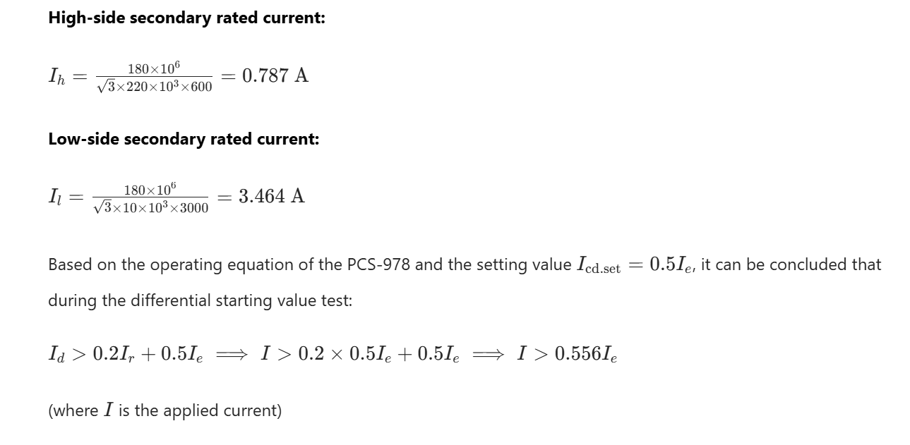
During the commissioning of transformer differential protection, for the pickup value commissioning where the starting segment is a horizontal straight line, the pickup value verification can be directly conducted by applying 1.05 times and 0.95 times the setting value—the operating current remains unchanged as the restraint current increases. However, for the starting segment with a sloped straight line, both the restraint current and operating current change continuously, making it unsuitable for commissioning with conventional methods. It is necessary to calculate by substituting the operating equation of the first segment of the broken line.

△ Relaystar-S70 Handheld Digital-analog Integrated Relay Protection Tester
This paper introduces how to use the Relaystar-S70 Handheld Digital-analog Integrated Relay Protection Tester to complete the sloped linear pickup value test of the PCS-978 transformer protection device. The steady-state percentage differential protection operating equation of the PCS-978 is as follows:
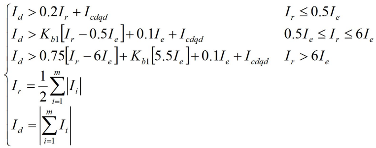
Where:
Ie = Rated current of the transformer.
I1...m = Currents of each side of the transformer.
Icdqd= Pickup value of the steady-state percentage differential protection.
Id = Differential current.
Ir = Restraint current.
kb1 = Setting value of the percentage restraint coefficient (0.2≤kb1≤0.75), which is fixed at kb1=0.5 in the device.

△ Operating Characteristic of Steady-state Percentage Differential Protection
1 Protection-related Settings
- Protection Setting Value and Control Word Configuration
|
Serial Number |
Setting Name |
Value |
Serial Number |
Setting Name |
Value |
|
01 |
Rated Capacity of Main Transformer High-voltage Side |
180MVA |
10 |
Longitudinal Differential Instantaneous Current Value |
5Ie |
|
02 |
Rated Capacity of Main Transformer Low-voltage Side |
90MVA |
11 |
Longitudinal Differential Pickup Current Value |
0.5Ie |
|
03 |
Low-voltage Side Wiring Mode |
11 |
12 |
Longitudinal Differential Instantaneous Protection Enable |
1 |
|
04 |
Primary Value of High-voltage Side PT |
220kV |
13 |
Longitudinal Differential Protection Enable |
1 |
|
05 |
Primary Value of Low-voltage Side PT |
10kV |
14 |
CT Breakage Blocking Differential Protection |
0 |
|
06 |
Primary Value of High-voltage Side CT |
600A |
- |
- |
- |
|
07 |
Secondary Value of High-voltage Side CT |
1A |
- |
- |
- |
|
08 |
Primary Value of Low-voltage Side CT |
3000A |
- |
- |
- |
|
09 |
Secondary Value of Low-voltage Side CT |
1A |
- |
- |
- |
- Protection Press Plate ConfigurationIn the "Press Plate Settings", set the "Main Protection" soft press plate to "1", set the "Maintenance" hard press plate to "1", disconnect the "Trip Output" hard press plate, and check that the optical fiber channel 1 of the protection device is in the loopback state.
2 Test Wiring and Configuration

△ PCS-978 Differential Protection Wiring Diagram
Connect the optical port 1 of the Relaystar-S70 to the No.4 optical port of the high-voltage side of main transformer B07, optical port 3 to the No.4 optical port of the low-voltage side of main transformer B09, and optical port 5 to the No.3 optical port of the high-voltage side of main transformer B07. The three optical fibers are the high-voltage side SV, low-voltage side SV and high-voltage side GOOSE respectively.
Map the IA, IB, IC of the Relaystar-S70 to the three-phase current of the high-voltage side, Ia, Ib, Ic to the three-phase current of the low-voltage side, and the input A, B, C to the trip switches of the high, medium and low sides respectively. Configure the relevant IEC61850 parameters.
3 Pickup Value Verification
- Pickup Value Verification with Three-phase Symmetrical Current Applied to High-voltage Side
① 1.05 Times Reliable Operation Verification: I=1.05×0.556×0.787=0.459AThe state sequence settings are as follows:
|
|
State 1 (Pre-fault) |
State 2 (Fault) |
|
IA/A |
0 |
0.459∠0° |
|
IB/A |
0 |
0.459∠240° |
|
IC/A |
0 |
0.459∠120° |
|
Ia/A |
0 |
0 |
|
Ib/A |
0 |
0 |
|
Ic/A |
0 |
0 |
|
Trigger Condition |
Key Trigger |
Time Trigger |
|
Input Type |
- |
- |
|
Test Time/ms |
- |
100 |
|
Delay after Trigger/ms |
0 |
0 |
△ 1.05 Times High-voltage Side Pickup Value Verification (Three-phase Test)
After starting the operation, trigger with the key. The differential protection operates, and the operation message is as follows:

△ 1.05 Times High-voltage Side Pickup Value Operation Message
② 0.95 Times Non-operation Verification: I=0.95×0.556×0.787=0.415AThe state sequence settings are as follows:
|
|
State 1 (Pre-fault) |
State 2 (Fault) |
|
IA/A |
0 |
0.415∠0° |
|
IB/A |
0 |
0.415∠240° |
|
IC/A |
0 |
0.415∠120° |
|
Ia/A |
0 |
0 |
|
Ib/A |
0 |
0 |
|
Ic/A |
0 |
0 |
|
Trigger Condition |
Key Trigger |
Time Trigger |
|
Input Type |
- |
- |
|
Test Time/ms |
- |
100 |
|
Delay after Trigger/ms |
0 |
0 |
△ 0.95 Times High-voltage Side Pickup Value Verification
After starting the operation, trigger with the key. The differential protection starts but does not operate, and the message is as follows:

△ 0.95 Times High-voltage Side Pickup Value Operation Message
- Pickup Value Verification with Single-phase Current Applied to High-voltage Side
The PCS-978 device processes the Y side with the formula Ih′=Ih−I0. When single-phase current is applied, 3I0=Ih and Ih′=32Ih. Therefore, the single-phase current applied to the high-voltage side is Ih=1.5Ih′.
① 1.05 Times Reliable Operation Verification: I=1.05×0.556×0.787×1.5=0.689AThe state sequence settings are as follows:
|
|
State 1 (Pre-fault) |
State 2 (Fault) |
|
IA/A |
0 |
0.689∠0° |
|
IB/A |
0 |
0 |
|
IC/A |
0 |
0 |
|
Ia/A |
0 |
0 |
|
Ib/A |
0 |
0 |
|
Ic/A |
0 |
0 |
|
Trigger Condition |
Key Trigger |
Time Trigger |
|
Input Type |
- |
- |
|
Test Time/ms |
- |
100 |
|
Delay after Trigger/ms |
0 |
0 |
△ 1.05 Times High-voltage Side Pickup Value Verification (Single-phase Test)
After starting the operation, trigger with the key. The differential protection operates, and the operation message is as follows:

△ 1.05 Times High-voltage Side Pickup Value Operation Message
② 0.95 Times Non-operation Verification: I=0.95×0.556×0.787×1.5=0.623AThe state sequence settings are as follows:
|
|
State 1 (Pre-fault) |
State 2 (Fault) |
|
IA/A |
0 |
0.623∠0° |
|
IB/A |
0 |
0 |
|
IC/A |
0 |
0 |
|
Ia/A |
0 |
0 |
|
Ib/A |
0 |
0 |
|
Ic/A |
0 |
0 |
|
Trigger Condition |
Key Trigger |
Time Trigger |
|
Input Type |
- |
- |
|
Test Time/ms |
- |
100 |
|
Delay after Trigger/ms |
0 |
0 |
△ 0.95 Times High-voltage Side Pickup Value Verification
After starting the operation, trigger with the key. The differential protection starts but does not operate, and the message is as follows:

△ 0.95 Times High-voltage Side Pickup Value Operation Message
- Pickup Value Verification with Three-phase Symmetrical Current Applied to Low-voltage Side
① 1.05 Times Reliable Operation Verification: I=1.05×0.556×3.463=2.021AThe state sequence settings are as follows:
|
|
State 1 (Pre-fault) |
State 2 (Fault) |
|
IA/A |
0 |
0 |
|
IB/A |
0 |
0 |
|
IC/A |
0 |
0 |
|
Ia/A |
0 |
2.021∠0° |
|
Ib/A |
0 |
2.021∠240° |
|
Ic/A |
0 |
2.021∠120° |
|
Trigger Condition |
Key Trigger |
Time Trigger |
|
Input Type |
- |
- |
|
Test Time/ms |
- |
100 |
|
Delay after Trigger/ms |
0 |
0 |
△ 1.05 Times Low-voltage Side Pickup Value Verification (Three-phase Test)
After starting the operation, trigger with the key. The differential protection operates, and the input module captures the operation time.
② 0.95 Times Non-operation Verification: I=0.95×0.556×3.463=1.829AThe state sequence settings are as follows:
|
|
State 1 (Pre-fault) |
State 2 (Fault) |
|
IA/A |
0 |
0 |
|
IB/A |
0 |
0 |
|
IC/A |
0 |
0 |
|
Ia/A |
0 |
1.829∠0° |
|
Ib/A |
0 |
1.829∠240° |
|
Ic/A |
0 |
1.829∠120° |
|
Trigger Condition |
Key Trigger |
Time Trigger |
|
Input Type |
- |
- |
|
Test Time/ms |
- |
100 |
|
Delay after Trigger/ms |
0 |
0 |
△ 0.95 Times Low-voltage Side Pickup Value Verification
After starting the operation, trigger with the key. The differential protection starts but does not operate, and the input module fails to capture the operation time.
- Pickup Value Verification with Single-phase Current Applied to Low-voltage Side
The PCS-978 device performs phase compensation for the phase-shifting mode of the Δ side with the formulas:Ila’=(Ila-Ilc)/1.732,Ilb’=(Ilb-Ila)/1.732,Ilc’=(Ilc-Ilb)/1.732,When single-phase current is applied to the low-voltage side, Il=1.732Il′.
① 1.05 Times Reliable Operation Verification: I=1.05×0.556×3.463×1.732=3.495AThe state sequence settings are as follows:
|
|
State 1 (Pre-fault) |
State 2 (Fault) |
|
IA/A |
0 |
0 |
|
IB/A |
0 |
0 |
|
IC/A |
0 |
0 |
|
Ia/A |
0 |
3.495∠0° |
|
Ib/A |
0 |
0 |
|
Ic/A |
0 |
0 |
|
Trigger Condition |
Key Trigger |
Time Trigger |
|
Input Type |
- |
- |
|
Test Time/ms |
- |
100 |
|
Delay after Trigger/ms |
0 |
0 |
△ 1.05 Times High-voltage Side Pickup Value Verification (Single-phase Test)
After starting the operation, trigger with the key. The differential protection operates, and the input module captures the operation time.
② 0.95 Times Non-operation Verification: I=0.95×0.556×3.463×1.732=3.163AThe state sequence settings are as follows:
|
|
State 1 (Pre-fault) |
State 2 (Fault) |
|
IA/A |
0 |
0 |
|
IB/A |
0 |
0 |
|
IC/A |
0 |
0 |
|
Ia/A |
0 |
3.163∠0° |
|
Ib/A |
0 |
0 |
|
Ic/A |
0 |
0 |
|
Trigger Condition |
Key Trigger |
Time Trigger |
|
Input Type |
- |
- |
|
Test Time/ms |
- |
100 |
|
Delay after Trigger/ms |
0 |
0 |
△ 0.95 Times High-voltage Side Pickup Value Verification
After starting the operation, trigger with the key. The differential protection starts but does not operate, and the input module fails to capture the operation time.
Based on the above test results, the verification of the 1.05 times and 0.95 times operation behaviors of the sloped pickup value is completed.
24-hours hot line 400-099-8859 technical hot line: 13971234137

Copyright © 2024 All rights Reserved.
备案号:鄂ICP备05010718号-1
