Contact: sales@haomai.net
NEWS
Company News
Case Practice | Injection-based Phasor Check for Newly Added Bays Before Commissioning Without Power Outage of Substation Bus
Enterprise News
Case Practice | Injection-based Phasor Check for Newly Added Bays Before Commissioning Without Power Outage of Substation Bus
Release Date: July 27, 2022 Wuhan Haomai Electric Power Automation Co., Ltd.
Test Location: A 110kV Smart Substation
Test Equipment: HTA/HTV Wireless Remote-controlled Digital Intelligent Current/Voltage Source, YD-300 Wireless Telemetry Voltmeter-Ammeter Phase Indicator
In general, the bus will not be de-energized when a substation adds new bays, making it impossible to apply primary voltage to the protection device of the newly added line. This paper introduces an injection-based phasor check test for the newly expanded bays using the HTA/HTV Wireless Remote-controlled Digital Intelligent Current/Voltage Source, which adopts the method of synchronously applying primary current and secondary voltage without power outage of the bus before substation commissioning.
1. Test Wiring
- The primary equipment of the substation adopts a fully enclosed GIS structure, among which the 111 switch bay is the original bay in normal operation, and the 116 switch bay is the newly added bay.

△ Primary System Diagram (Partial Bays)
- Since other bays are live, wiring can only be carried out on the 116 bay. Wiring inside the GIS for primary equipment is not allowed. On-site inspection shows that the 1168 earthing switch is easy to open. Therefore, for wiring, it is necessary to close the 116 switch and the 1165 earthing switch, and open all other switch earthing switches in this bay. The current flows through the CT via the 1168 earthing switch, then through the 226 switch, and finally flows into the ground via the 1165 earthing switch to form a current loop. The 110kV line protection is installed locally, and the voltage is directly applied to the secondary side of the line protection device through the voltage source.

△ On-site Wiring Diagram
2. Test Settings and Operation Method
Inject primary current and voltage through CT and PT, then check the amplitude and phase on the protection device to verify all secondary circuits and polarities. The ratio of the CT protection winding of the test bay is 1200A/5A.
- First, perform standalone operation: apply primary current and secondary voltage respectively, and check whether the sampled values are correct on the protection sampling interface. Confirm that the test wiring is correct after checking the sampled values.
- Power on the current source and voltage source and set them to the remote control operation state. The remote control host will automatically search for the current source and voltage source; check whether the remote control signal is normal.
- Set parameters on the remote control host as follows:
|
Phase |
Set Amplitude |
Set Phase |
|
UA |
60V |
∠0° |
|
UB |
60V |
∠240° |
|
UC |
60V |
∠120° |
|
IA |
60A |
∠0° |
|
IB |
120A |
∠240° |
|
IC |
180A |
∠120° |
△ Parameter Setting Diagram
After completing the parameter settings, click to start the test. The current source and voltage source start outputting, and the collected values can be viewed on the host.
3. Test Results
Keep the primary current and secondary voltage outputting. Select phase A voltage and phase A current, and check whether the phasor polarity is correct by reading the secondary values collected by the YD-300 Wireless Telemetry Voltmeter-Ammeter Phase Indicator.
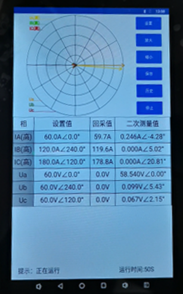
△ Test Results
Test Conclusion: The secondary value converted from the applied primary current should be 60A × 5/1200 = 0.25A, and the secondary voltage is 58V, indicating that the sampled values are correct. The primary current flows into the CT from P2 to P1, while the secondary clamp meter measures the current flowing from IAN to IA. Both the primary and secondary sides adopt reverse polarity injection, resulting in the measured actual current phase of -4.28° (close to 0°), which is correct. Based on the above data, it is concluded that the secondary circuit, phase sequence, phase and polarity of this bay are all correct.
24-hours hot line 400-099-8859 technical hot line: 13971234137

Copyright © 2024 All rights Reserved.
备案号:鄂ICP备05010718号-1
