Contact: sales@haomai.net
NEWS
Company News
Fast and Efficient! Search Method for Generator-transformer Unit Percentage Differential Boundary Curve
Protection Device: RCS-985A Generator-transformer Unit Protection Device
Test Equipment: Relaystar-1600S Handheld Relay Protection Tester
The boundary curve of generator-transformer unit percentage differential protection is frequently involved in power plant protection commissioning, and the commissioning process may require a large number of formula calculations. This paper introduces one of the fast search methods for the generator-transformer unit percentage differential boundary curve, discards complicated formula conversion, and uses the dedicated generator-transformer unit module of the Relaystar-1600S Handheld Relay Protection Tester to commission the RCS-985A generator-transformer unit protection device.

△ Relaystar-1600S Handheld Relay Protection Tester
The front section of the percentage differential operating characteristic curve of the RCS-985A generator-transformer unit protection device is a parabola, and the rear section is a straight line with a slope. The following describes the search method for the boundary curve.
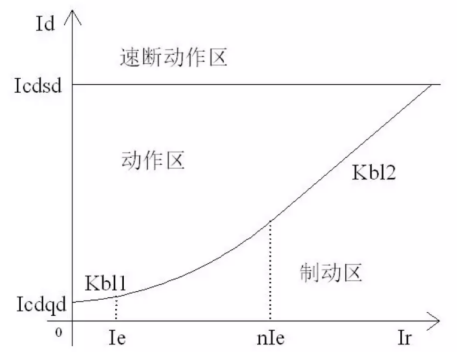
△ Differential Operating Characteristic Curve
1 Protection-related Settings
- Protection Setting Value and Control Word Configuration
- Protection Press Plate Configuration
In the "Press Plate Settings", set the "Generator-transformer Unit Differential Protection" soft press plate to "1", set the "Maintenance" hard press plate to "1", and disconnect the "Trip Output" hard press plate.
|
Serial Number |
Setting Name |
Value |
Serial Number |
Setting Name |
Value |
|
01 |
Rated Capacity of Main Transformer |
360MVA |
09 |
Secondary Side of Generator TA |
5A |
|
02 |
Primary Rated Voltage of High-voltage Side |
242kV |
10 |
- |
- |
|
03 |
Primary Side of High-voltage Side TA |
1250A |
11 |
Generator-transformer Unit Differential Pickup Value |
0.4Ie |
|
04 |
Secondary Side of High-voltage Side TA |
1A |
12 |
Generator-transformer Unit Differential Instantaneous Value |
5Ie |
|
05 |
Rated Capacity of Generator |
330MVA |
13 |
Initial Slope of Percentage Restraint |
0.1 |
|
06 |
Power Factor of Generator |
0.94 |
14 |
Maximum Slope of Percentage Restraint |
0.7 |
|
07 |
Primary Rated Voltage |
20kV |
15 |
Differential Instantaneous Protection Enable |
1 |
|
08 |
Primary Side of Generator TA |
15000A |
16 |
Percentage Differential Protection Enable |
1 |
2 Test Wiring
The Relaystar-1600S is a 6U6I type relay protection tester. For wiring, connect IA, IB, IC to the protection winding of the high-voltage side TA of the main transformer, connect Ia, Ib, Ic to the neutral point side CT protection winding of the generator, and connect a set of trip output to the input A of the tester. The test can be started after the wiring is completed.

△ Wiring Diagram
3 Test Method
Calculate the secondary rated current of each side according to the protection setting values
Secondary rated current of the high-voltage side of the main transformer:
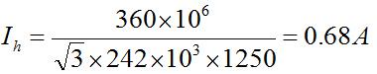
Secondary rated current of the generator neutral point side:
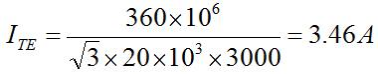
- Inject Balancing CurrentAccording to the above test wiring and analysis, the six-phase current output of the Relaystar-1600S can be used to inject the generator-transformer unit differential balancing current. Apply a current of 0.68A on the high-voltage side and 3.46A on the neutral point side, and check the protection sampling data: the generator-transformer unit differential current is 0Ie, and the restraint current is 1Ie.

△ Balancing Current Settings
- Search for Percentage Boundary CurveOpen the dedicated generator-transformer unit differential module, and set the following parameters according to the setting values: differential instantaneous pickup value is 5Ie, differential pickup threshold is 0.4Ie, the phase adjustment of RCS-985A is set from Y side to Δ side, directly input the secondary rated current as the balance coefficient, and keep other parameters as default. Fill in the setting values in the percentage boundary parameter interface: initial slope is 0.1, maximum slope is 0.7, restraint current multiple is 6, and add the sequence.


△ Test Parameter Settings
After the above parameters are set, start the test. The Relaystar-1600S will automatically perform bidirectional search for the operating boundary and mark points on the boundary between the operating region and the restraint region.
04 Test Conclusion
The protection device will operate continuously during the test, and the operation message shall be recorded.

△ Percentage Differential Operation Message
The Relaystar-1600S records the operating boundary curve, from which the percentage boundary curve of the generator-transformer unit differential protection can be directly observed. The data is consistent with the theoretical boundary, meeting the test requirements.

△ Percentage Boundary Curve
24-hours hot line 400-099-8859 technical hot line: 13971234137

Copyright © 2024 All rights Reserved.
备案号:鄂ICP备05010718号-1
