Contact: sales@haomai.net
NEWS
Company News
Case Practice | Vector Check Test for 500kV Main Transformer Differential Protection
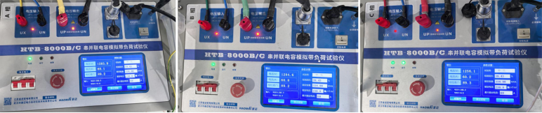
The HTB-8000 Large Transformer Primary Current Injection Test Device was adopted to conduct a vector check on the 500kV main transformer differential protection. Voltage was boosted from the primary side, and through-current was achieved using the transformer’s own short-circuit impedance. This method enabled one-step current injection for the external CTs, bushing CTs, and common winding CTs on the high (medium) voltage side of the main transformer, as well as the external CTs and bushing CTs on the low voltage side. It verified the vector correctness of the main transformer longitudinal differential protection, phase differential protection, split-side differential protection, and low-voltage side zone differential protection. The polarity correctness of the main transformer protection vector can be directly judged by the differential current value, which greatly improves the power transmission efficiency.
1. Test Mode
The transformer of a 500kV substation adopts the Y/Δ-11 connection mode. The following describes the test method with current injection from the medium-voltage side to the low-voltage side.

△ Transformer Nameplate
When the transformer tap is at the rated position, the short-circuit impedance from the medium-voltage side to the low-voltage side can be calculated using the nameplate parameters:
Z= U*U/S*short-circuit impedance(%)= (230kV*230kV)/(3*334MVA)*39.43%=20.82Ω
When a current of 60A is applied to the medium-voltage side, the corresponding output voltage is 60A×20.82Ω=1250V. The loop current generated by short-circuiting the low-voltage side of the transformer is 60A×230kV/1.732/36kV=221A.
Current was injected from the earthing switch of a line bay on the medium-voltage side, flowing through the CT of the medium-voltage side bay of the main transformer to the main transformer. The induced current on the low-voltage side was grounded via the voltage transformer earthing switch. The test device output 1250V in three-phase synchronization. Sampling data was checked on the protection device to verify the vector correctness of the main transformer protection.

△ Current Injection Loop
2. Test Wiring
Since the medium-voltage side uses GIS fully enclosed equipment, it was necessary to remove the earthing switch at the current injection point before test wiring, so as to apply three-phase voltage. The voltage transformer earthing switch on the low-voltage side was closed.

△ On-site Wiring
3. Test Initiation
After completing the primary circuit wiring, parameters were set on the test device, and the booster was adjusted to the test voltage and current values.
4. Test Results
The transformation ratios of the external CTs, bushing CTs, and common winding CTs on the medium and low voltage sides of the substation are all 4000:1, with polarities pointing from the busbar to the main transformer.
When a current of 60A was applied to the medium-voltage side, the secondary currents of the external CTs and common winding CTs on the medium-voltage side were both 0.015A. With the medium-voltage side voltage as the reference, the transformer coil acts as a purely inductive load, causing the current to lag the voltage by 90°. The phase angle of the external CTs was -90° positive sequence, while that of the common winding CTs was 90° positive sequence.
The induced current on the low-voltage side was 221A. The secondary current of the bushing CTs was 0.055A with a phase angle of 90° positive sequence. The secondary current of the external CTs was 0.095A; as the external CTs on the low-voltage side adopt Δ connection, the phase angle was 120° positive sequence.
The transformer carried through-current, which is equivalent to an external fault. The theoretical differential currents of the longitudinal differential protection, split-side differential protection, and phase differential protection should all be zero. After the current was raised, the sampling currents and differential currents of each side were checked on the main transformer protection device.

△ Sampling Current

△ Differential Current
The on-site test data is shown in the table below:
|
Type |
Transformation Ratio |
Phase A (A/V) |
Phase B (A/V) |
Phase C (A/V) |
|
Medium-voltage Side |
4000:1 |
0.015∠274° |
0.015∠154° |
0.015∠38° |
|
Low-voltage Bushing |
4000:1 |
0.055∠91° |
0.056∠331° |
0.055∠214° |
|
Low-voltage Side |
4000:1 |
0.095∠120° |
0.095∠0° |
0.095∠240° |
|
Common Winding |
4000:1 |
0.015∠90° |
0.015∠334° |
0.015∠210° |
|
Longitudinal Differential Current |
/ |
0 |
0 |
0 |
|
Phase Differential Current |
/ |
0 |
0 |
0 |
|
Split-side Differential Current |
/ |
0 |
0 |
0 |
|
Low-voltage Zone Differential Current |
/ |
0 |
0 |
0 |
A comparison between the actual sampling data and differential current of the protection device was consistent with the theoretical calculation results. It can be concluded that the polarity vectors of all differential protection functions are correct.
24-hours hot line 400-099-8859 technical hot line: 13971234137

Copyright © 2024 All rights Reserved.
备案号:鄂ICP备05010718号-1
