Contact: sales@haomai.net
NEWS
Company News
[Case Analysis] Calibration of Error Curve and Accuracy Limit Factor for Current Transformers
When conducting current transformer (CT) tests, we can measure the transformation ratio, phase error, ratio error, volt-ampere characteristic curve, etc. For a more accurate understanding of CT performance, it is also necessary to calculate and analyze parameters such as unsaturated inductance, residual magnetism coefficient, secondary time constant, hysteresis curve, limit electromotive force, accuracy limit factor and error curve. This paper mainly introduces how to calibrate protective CTs using the error curve and accuracy limit factor.
Composite Error: In a steady state, the root mean square value of the difference between the instantaneous value of the primary current and the instantaneous value of the secondary current multiplied by the rated current ratio (transformation ratio).
Error Curve: When a short-circuit current flows through the primary winding of a protective current transformer, the transformer transmits current information to the secondary side. To ensure the correct operation of the relay protection device, the transformer must have a certain accuracy, i.e., the composite error does not exceed the limit values (5% and 10% are the two common limits). The relationship curve between the primary current multiple and the secondary load while keeping the error limit constant is generally referred to as the error curve.
Note: When a CT is under overcurrent conditions, the secondary current is no longer a sine wave due to the distorted waveform of the excitation current. The CT error characteristics cannot be specified directly by the current error and phase difference, and the composite error must be used instead.
Accuracy Limit Factor (ALF, or Kalf): In a steady state, the ratio of the maximum primary current value (Ipal) that a CT can carry while meeting the composite error requirement to the rated primary current (Ipn), i.e., Kal=Ipal/Ipn.
The standard values of the accuracy limit factor are generally 5, 10, 20, 30, 40.
For example, if a CT nameplate is marked 10P30, the accuracy class is 10P and the accuracy limit factor is 30. When the short-circuit current does not exceed 30 times the rated current (IN), the composite error of the CT will not exceed 10%.
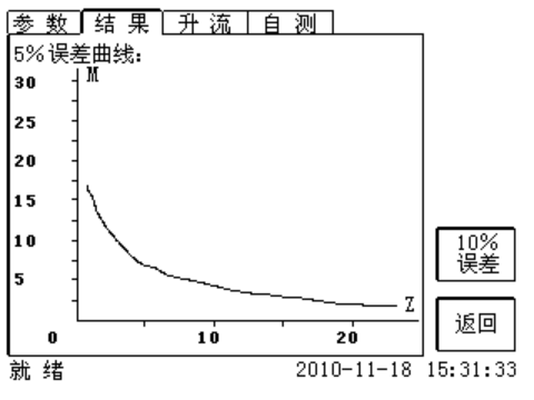
△ 5% Error Curve

△ 5% Error Data
1. How to Judge CT Performance Using the Error Curve?
- Check and compare the measured secondary load value against the error data table or error curve.
- Deduce the error curve from the excitation characteristic data:M=I1NI1M=Kn×I2NKn×I1=I2N10I0
Where:I1M – Maximum short-circuit current on the primary side;I1N – Rated primary current;I2N – Rated secondary current;I2 – Secondary current;I0 – Excitation current;Z2 – Secondary winding impedance;E0 – Induced electromotive force of the secondary winding;Kn – Rated current ratio;ZB – Maximum allowable load impedance at 10% error;M – Multiple of the maximum short-circuit current on the primary side.
- How to Obtain the Error Curve?

△ Wiring Diagram

△ Parameter Setting
The CTP-120P Transformer Tester is used for the test in this case, and the test result analysis is as follows:
Example: A CT nameplate is marked 5P10. The maximum allowable secondary impedance is 2.8Ω obtained from the 5% error curve, and the CT performance can be judged against the protection requirements by the actual measured value of the secondary impedance.
- If the measured equivalent load impedance is 1Ω:It indicates that the CT can drive the secondary connected loads (including cables, protection devices, measurement and control devices, meters, etc.). The composite error is less than 5% during the protection action, ensuring the correct operation of the protection device.
- If the measured equivalent load impedance is 3Ω:It indicates that the CT cannot drive the secondary connected loads, and the CT will saturate in advance, leading to protection refusal to operate.
3. Calibration of the Accuracy Limit Factor
Conduct the excitation test using the CTP-120P Transformer Tester with the wiring method shown in the above figure, and fill in the actual load or rated load in the load field on the parameter setting page.

△ Accuracy Limit Factor Test Result
Note: If the measured ALF is greater than or equal to the rated value, the CT is qualified, and other tests can be carried out subsequently. If the measured ALF is less than the rated value, the CT is judged as unqualified.
Example: A CT nameplate is marked 10P20 with a transformation ratio of 1000:1, and the protection instantaneous trip setting value is 20A. How to judge the influence of ALF on the protection action?
- If the measured value is 25:It indicates that the maximum primary operating current of the CT can reach 25kA, which is converted to the secondary side as a maximum short-circuit current of 25A with a composite error of less than 10%, ensuring the correct operation of the instantaneous trip protection.
- If the measured value is 18:It indicates that the maximum primary operating current of the CT can only reach 18kA, which is converted to the secondary side as a maximum short-circuit current of only 18A, failing to reach the instantaneous trip setting value and resulting in protection refusal to operate.
24-hours hot line 400-099-8859 technical hot line: 13971234137

Copyright © 2024 All rights Reserved.
备案号:鄂ICP备05010718号-1
