Contact: sales@haomai.net
NEWS
Company News
Commissioning Method for Generator Overexcitation Protection
Generators or transformers may operate in an overexcitation state due to voltage rise or frequency drop, and prolonged overexcitation operation will damage the generator or transformer. For large-capacity generators and transformers, overexcitation protection shall be installed. Overexcitation protection reflects the overexcitation multiple, which is the ratio of voltage to frequency. An increase in the voltage or a decrease in the frequency of a generator or transformer may cause overexcitation, namely:
Uf=U/f=B/Be
Where: Uf – overexcitation multiple;
U,f – actual voltage and frequency;
B,Be – actual working magnetic flux density and rated magnetic flux density of the iron core.
The AC voltage input to the generator overexcitation protection is taken from the secondary phase-to-phase voltage of the generator terminal PT, and its inverse time action curve is matched with the overexcitation capacity characteristic curve of the generator.

△ Inverse Time Action Characteristic of Overexcitation Protection
The commissioning of generator overexcitation protection is a key part of generator protection commissioning. The following is an example to introduce the commissioning method.
1 Overexcitation Protection Setting Sheet of a Generator Protection Device (Partial)
|
No. |
Setting |
Value |
No. |
Setting |
Value |
|
1 |
Multiple Uf1 |
1.1 |
6 |
Time tf1 |
2.0s |
|
2 |
Multiple Uf2 |
1.2 |
7 |
Time tf2 |
1.0s |
|
3 |
Multiple Uf3 |
1.3 |
8 |
Time tf3 |
0.5s |
|
4 |
Multiple Uf4 |
1.4 |
9 |
Time tf4 |
0.2s |
|
5 |
Multiple Uf5 |
1.5 |
10 |
Time tf5 |
0s |
Note: The inverse time overexcitation protection control word shall be set to "1" during the test.
2 Test Wiring
Connect the output voltage terminals UA, UB, UC, UN of the Relaystar-S60 Handheld Relay Protection Test System to the generator terminal voltage terminal block of the generator protection device, and connect the tripping action contact of the overexcitation protection to the input terminal A and the common terminal of the Relaystar-S60.
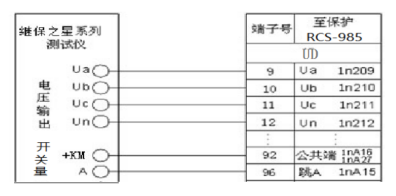
△ Wiring of Overexcitation Protection
3 Test Software and Parameter Setting: Select the AC Test Interface
The test method is to fix the voltage frequency and change the applied multiple of the rated voltage to realize the voltage increase, and the overexcitation inverse time characteristic can be described by multi-point data.
Parameter Setting for Multiple Uf1.1
The overexcitation AC voltage is taken from the secondary phase-to-phase voltage of the generator terminal PT, i.e., the rated line voltage of 100V, and the corresponding phase voltage of 1.1 times is 57.735V×1.1=63.508V. The phase is positive sequence phase, and the voltage frequency is 50Hz.
Parameter Setting for Multiple Uf1.2
The overexcitation AC voltage is taken from the secondary phase-to-phase voltage of the generator terminal PT, i.e., the rated line voltage of 100V, and the corresponding phase voltage of 1.2 times is 57.735V×1.2=69.282V. The phase is positive sequence phase, and the voltage frequency is 50Hz.
Parameter Setting for Multiple Uf1.3
The overexcitation AC voltage is taken from the secondary phase-to-phase voltage of the generator terminal PT, i.e., the rated line voltage of 100V, and the corresponding phase voltage of 1.3 times is 57.735V×1.3=75.055V. The phase is positive sequence phase, and the voltage frequency is 50Hz.
The parameters of other multiples can be obtained in the same way. The figure below shows the parameter setting interface for the multiple Uf1.1.

4 Test Method and Results
After starting the test according to the set parameters and wiring, the overexcitation protection operates, and the corresponding message information is displayed on the protection device. The input terminal A of the Relaystar-S60 collects the action information. The overexcitation inverse time action curve can be described by increasing the voltage multiple for multiple test points.
24-hours hot line 400-099-8859 technical hot line: 13971234137

Copyright © 2024 All rights Reserved.
备案号:鄂ICP备05010718号-1
