Contact: sales@haomai.net
NEWS
Company News
Technical Practice | Commissioning Method for Second Harmonic Restraint of Transformer Differential Protection
Protection Device: RCS-978 Series Transformer Integrated Protection Device
Test Equipment: Relaystar-S60 Handheld Relay Protection Test System
When a transformer is closed at no-load, the magnetic flux in the iron core cannot change abruptly, which generates a large transient DC magnetic flux component superimposed on the steady-state magnetic flux. This leads to severe saturation of the transformer iron core and a huge magnetizing inrush current on the closing side of the transformer. Since the magnetizing inrush current only exists on one side of the transformer, it becomes a massive unbalanced current that may cause the ratio restraint protection to maloperate.
The RCS-978 Series Transformer Integrated Protection Device identifies the magnetizing inrush current by detecting the content of the second harmonic and third harmonic in the three-phase differential current. The current is judged as a magnetizing inrush current when the harmonic content exceeds a certain proportion of the fundamental wave content of the differential current. If any phase among the three phases is judged to have a magnetizing inrush current, only the ratio differential element of that phase is blocked. The judgment equation is as follows:
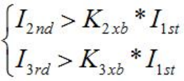
I2nd and I3rd represent the second harmonic and third harmonic in the differential current of each phase, respectively.
I1st represents the corresponding fundamental wave of the differential current.
k2xb and k3xb represent the setting values of the second harmonic restraint coefficient and third harmonic restraint coefficient, respectively. In the device, k2xb is fixed at 0.15, and k3xb is fixed at 0.2. If any phase among the three phases is judged to have a magnetizing inrush current, only the ratio differential element of that phase is blocked.
This article introduces the second harmonic commissioning test of the RCS-978 using the harmonic test module of the Relaystar-S60 Handheld Relay Protection Test System.

△ Relaystar-S60 Handheld Relay Protection Test System
1 Test Principle
The second harmonic restraint coefficient is set to 15%: the differential protection will be blocked when the second harmonic content in the fundamental wave component is greater than 15%, and the protection will be enabled only when the second harmonic content is less than 15%.
It is recommended to perform single-side and single-phase superposition during the test. Superposition on multiple phases will cause mutual interference of the second harmonic in different phases, making it difficult to determine the second harmonic content in the differential current.
2 Test Wiring

△ Wiring Diagram for Differential Harmonic Test
Connect the current output terminals IA and IN of the Relaystar-S60 to the high-voltage side current terminals 1IAH and 1INH of the protection device respectively, with no wiring for the other phases.
Connect the input contact A of the Relaystar-S60 to the trip output contact of the differential protection of the protection device.
Connect the common terminal +KM of the Relaystar-S60 to the common terminal of the protection device.
3 Test Method
In the Harmonic Test menu, the simple method for testing the harmonic restraint coefficient is as follows: apply a single-phase current to only one side of the transformer, then adjust its harmonic content (generally by gradually reducing the harmonic content) to make the differential protection switch from the restraint state to the operating state.
Key Note for Single-phase Harmonic Test: The single-phase current applied for differential operation must be greater than 1.732 times the setting value.
1) Differential Operation Test
Set the fundamental wave value of phase IA in the harmonic test to a current of 1A, start the test and observe the operation of the protection device. Increase the fundamental wave current if the protection does not operate.

2) Test Parameter Setting
Select IA as the variable phase;
Select percentage of fundamental wave as the harmonic representation method;
Set the variable step size to 1%;
Select manual adjustment mode.

3) Harmonic Setting
Set the initial percentage of the second harmonic to 20% in the test item, which means the test starts with a 20% second harmonic content and decreases gradually to simulate the process from harmonic restraint to harmonic release. The current waveform diagram at the bottom right can display the 1A current waveform with 20% harmonic content.

4) Test Operation
After starting the test, the 20% harmonic content will restrain the differential protection (the protection is initiated but not operated). During the test, gradually reduce the output value of the second harmonic current according to the set step size until the differential protection operates.
5) Test Result
When the protection device operates, the harmonic content displayed on the test interface should be 15%, and the input A of the Relaystar-S60 will record the operation time at this moment.
The third harmonic restraint coefficient (20%) can be calibrated using the same method.
24-hours hot line 400-099-8859 technical hot line: 13971234137

Copyright © 2024 All rights Reserved.
备案号:鄂ICP备05010718号-1
