Contact: sales@haomai.net
NEWS
Company News
Case Practice | Charge and Discharge Test Method for Storage Batteries
Test Equipment: FDT-220 DC System Comprehensive Tester
Project Location: A 110kV Substation

△ Schematic Diagram of DC Power Supply System
Preparations for Battery Discharge Test
1) Disconnect the charging of the storage battery by the charging bus +L1
Realize this by opening the incoming line air switches 1KK, 2KK and 3KK of the charging modules, i.e., disconnect the connection of AC power supply > charging module > charging bus > step-down silicon chain > control bus.
2) Maintain the connection between the charging bus +L1 and the storage battery
Keep the battery air switch QF3 closed, i.e., maintain the connection of storage battery bank > charging bus > step-down silicon chain > control bus. Since the connection of AC power supply > charging module > charging bus > step-down silicon chain > control bus has been disconnected in the previous step, if the incoming line of the control module loses power or the module itself fails at this time, the storage battery bank will supply power to the DC bus through the step-down silicon chain.
Without a wireless module, accurate monitoring of single cells is impossible, and test data such as the discharge voltage of each cell needs to be repeatedly recorded during discharge. The use of the FDT-220 DC System Comprehensive Tester and battery cell wireless detection module will greatly improve the efficiency of the battery charge and discharge test.
Test Procedures
1) Open the incoming line air switches of the three charging modules before the test
At this time, the Module Fault and System Fault signal lights on the DC charging panel are on.

△ Fault Signal Lights On

△ FDT-220 DC System Comprehensive Tester

△ Battery Cell Wireless Detection Module
- Connect the battery cell wireless detection module to battery cells

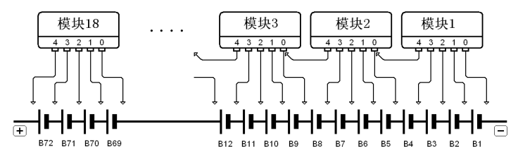
△ Wiring Schematic Diagram
There are 5 jacks on the side of the module, into which 5 detection wire clamps can be inserted, named as No.0 jack (black), No.1 jack (blue), No.2 jack (green), No.3 jack (yellow) and No.4 jack (red) in sequence. The 5 jacks can be inserted with the corresponding detection wire clamps respectively. The detection module is powered by the No.4 and No.0 wire clamps, and the voltage between them must be greater than 3V. When the detection module is installed correctly, the communication light is on and flashes when sending and receiving data.
△ Actual Wiring Diagram
3) Equipment Wiring
First perform power supply wiring; the device can be powered by either AC or DC power. DC power is generally used for the discharge test, and the storage battery bank is directly used as the power source. When the storage battery bank is used for power supply, these two wires also serve as discharge load lines. Since the storage battery bank is connected to the charging bus and the common bus, the power supply wires (discharge load lines) can be directly clamped to the busbars.
In the figure below, +WO is the charging bus, and -WO and -WC are the common buses.


4) Parameter Setting

Open the software main interface and click the Open File button on the toolbar. In the file path dialog box, find the corresponding discharge data file (read from the discharge tester host, file extension: ***.FDT). The interface displays the default battery bank terminal voltage curve, and the data display and browsing area on the right allows viewing of various characteristics, curves, bar charts and data tables of battery discharge.
- Disconnect the incoming line air switches of the charging modules

Send out Module Fault and System Fault signals, and the corresponding signal lights are on.
- Check the voltage before discharge

7) Start the test
Close the fan air switch and discharge air switch as prompted to start the test.

△ Real-time Discharge Data

△ Discharge Current Displayed on the Centralized Monitor
8) Record Data
During discharge, record the voltage data and discharge curves displayed on the monitoring system every hour.

9) End of Discharge
When the discharge time expires, the FDT-220 DC System Comprehensive Tester automatically opens the discharge air switch, and the discharge is completed.

10) Charge the Storage Batteries
The storage batteries need to be charged after discharge. Close the incoming line air switches of the charging modules, and the centralized monitor will automatically control the charging of the storage batteries at this time. Charge the storage batteries with a charging current of 20A according to the parameter settings.

△ Current Display of the Charging Module and Control Module

11) Inspection after Charging Completion
When the FDT-220 DC System Comprehensive Tester is used for automatic constant current discharge of the storage battery bank, it can automatically and continuously adjust the discharge current to achieve constant current discharge at a set current. During discharge, the device will automatically stop discharging when the battery bank terminal voltage or single cell voltage (when matched with a wired or wireless battery test system) drops to the set lower limit, or when the set discharge time is reached. The discharge current, voltage, time and discharge curves are displayed in real time during discharge, and the data is stored in the device and can be uploaded to a PC. The built-in management and analysis software supports query, analysis and report output of discharge data.
The charge and discharge test of storage batteries can activate the inside of the batteries, and the voltage of the battery bank becomes more balanced after charging and discharging. Matched with the battery cell wireless detection module, the voltage and discharge curve of each cell can be monitored by wireless communication during discharge and charging, and the system can automatically alarm and pause or resume discharge when any cell voltage drops below the lower limit. The wireless monitoring system can also be used independently to monitor the charging and floating charge operation status of each storage battery online. Adopting a special discharge load and advanced control mode, the discharge current can be continuously adjusted in a wide range with high constant current accuracy. It can be connected in parallel with constant current load modules to meet the requirements of larger discharge current, and is equipped with a discharge protection function that automatically stops discharging when the single cell voltage or battery bank terminal voltage drops below the set value or the set discharge time is reached.
Finally, after the charging is completed, check whether the system indications are normal, and measure and record the voltage of all battery cells.
24-hours hot line 400-099-8859 technical hot line: 13971234137

Copyright © 2024 All rights Reserved.
备案号:鄂ICP备05010718号-1
