Contact: sales@haomai.net
NEWS
Company News
Case Practice | Relay Protection Phasor Check Before Commissioning of 500kV Smart Substation
Test Equipment: HTA-1300 Single-phase Digital Intelligent High-current Source, HTV-6000 Three-phase Digital Intelligent High-voltage Source, YD-300 Wireless Telemetry Voltmeter-Ammeter Phase Indicator
Test Method: Adopt the substation commercial power supply as the reference to replace the traditional remote control synchronization method
01 Wiring Method
- Voltage Source Wiring: Connect the HTV-6000 Three-phase Digital Intelligent High-voltage Source to the phase A of the secondary voltage terminal on the protection panel, and inject a secondary voltage of 57.7V as the reference benchmark.
- Current Source Wiring (Taking one bay of the substation as an example):
Power Supply Requirement for Current Source: Take power from the substation's 220V commercial power supply to power the devices. A single 220V power supply can be taken from the standby three-phase switch of the voltage cabinet to power three single-phase current sources.
Close the isolation switch Q9 1684, close the switch Q0 168, and close the earthing switch 16880. Disconnect the isolation switch Q1 1681, disconnect the earthing switch 16800, and disconnect the line earthing switch 16340.
Connect three HTA-1300 Single-phase Digital Intelligent High-current Sources to the three-phase currents IA, IB, IC respectively through the 35kV leads, and form a current loop with IN via the isolation switch 1684, switch 168 and earthing switch 16880.

△ Three-phase Digital Current Source Wiring Diagram
- Disconnect the isolation switches connecting other bays to the 35kV busbar.
02 Test Procedure
The single-phase digital current source is powered by AC220V, and the three-phase digital voltage source is powered by AC220V. Set each phase of current and voltage to different amplitude states to check whether the current and voltage phase sequence is correct.
Inject the secondary voltage value from the protection panel as the reference and inject the primary current value into the CT. Check the amplitude and phase on the YD-300 Wireless Telemetry Voltmeter-Ammeter Phase Indicator to verify all secondary circuits and polarities. The ratio of the CT protection winding in this substation is 600A/1A.

△ Single-phase Digital Current Source Wiring
- Set Parameters on the Device Host: Output three-phase current of 120A and three-phase voltage of 57.735V.
|
Item |
Amplitude (V/A) |
Phase (°) |
|
UA |
57.735 |
0 |
|
UB |
57.735 |
240 |
|
UC |
57.735 |
120 |
|
IA |
120 |
0 |
|
IB |
120 |
240 |
|
IC |
120 |
120 |
(This scheme adopts commercial power supply, with phase A live wire of the commercial power as the reference)
- Click Start Test to activate the output of the current source and voltage source. Read the corresponding values on the YD-300 and compare them with the sampling values of the protection device. The sampling amplitude and phase displayed on the protection device are consistent with those shown on the YD-300. Thus, it can be concluded that the secondary circuit, phase sequence, phase and polarity of this bay are all correct.

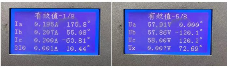
△ YD-300 Wireless Telemetry Voltmeter-Ammeter Phase Indicator Display Values
△ Protection Device Sampling Values
03 Test Conclusion and Analysis
Convert the applied primary value to the secondary value: 120A/600=0.2A, which is basically consistent with the sampling amplitude of the YD-300. The three-phase phase is in positive sequence.
The current flows into the CT primary side from P2 and out from P1, so the set phase of current and voltage differs by 180°. Due to the phase shift caused by the inductive reactance of the line and PT, there may be a small-range deviation in the phase measured by the protection device. It can be concluded that the secondary circuit, phase sequence, phase and polarity of this bay are all correct.
- For newly-built substations or newly added bays, applying primary current and voltage is conducive to checking the entire circuit, polarity and phase, improving the reliability of power transmission.
- This test adopts hardware transformation and upgrading, using commercial power as the reference phase, which is more intuitive and convenient, avoiding the external interference impact on wireless communication synchronization.
- The test with three-phase independent current sources allows flexible adjustment according to on-site conditions.
24-hours hot line 400-099-8859 technical hot line: 13971234137

Copyright © 2024 All rights Reserved.
备案号:鄂ICP备05010718号-1
