Contact: sales@haomai.net
NEWS
Company News
Case Practice | Test Method for Voltage Transformers
The CTP Series Transformer Tester is a new-generation high-precision instrument independently developed by Wuhan Haomai Electric Power based on low-frequency conversion technology, designed for testing the excitation characteristics, ratio and polarity of current transformers (CT) and voltage transformers (PT). Boasting comprehensive test functions and an accuracy of up to 0.05%, it is suitable for testing various types of CTs and PTs. The device is lightweight and portable, capable of conducting tests on transformers with large transformation ratios. It features fast testing speed, supports on-the-spot printing of test results or batch export of test reports, and can be used with analysis software to quickly and accurately determine whether transformers meet relevant standards.
Test Item: Incoming Line PT Test of 10kV Switchgear
Test Equipment: CTP Series Transformer Tester
Test Object: Incoming Line PT of 10kV Switchgear
01 Test Wiring

△ Wiring Diagram
Wiring Method for PT DC Resistance and Excitation Test
Take two sets of secondary test wires: connect the red set to terminals S1 and S2, and the yellow set to terminals M1 and M2.
Connect the opposite end to the secondary winding of the transformer. First, short-circuit S1 to M1 and S2 to M2 on the opposite end, then connect them to one group of the transformer windings, keeping other secondary windings open-circuited.


△ On-site Wiring
On-site Test Wiring Requirements
During the test, completely disconnect the primary side of the PT and the common terminal N. Meanwhile, keep other secondary windings of the PT open-circuited.
02 PT Test Parameter Settings
- ID & Winding No.: Letters and numbers can be entered.
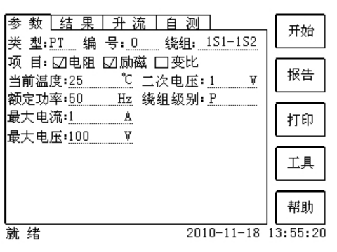
- Rated Secondary Voltage: The rated voltage of the PT secondary side.
- Accuracy Class: The accuracy class of the tested winding, with options such as Class P available.
- Current Temperature: The temperature of the winding during the test, generally input as the ambient temperature at the time of testing.
- Rated Frequency: Selectable values are 50Hz or 60Hz.
- Maximum Test Voltage: The maximum power frequency equivalent voltage output by the device. This voltage must be higher than the knee voltage, generally set to 50V–100V above the secondary voltage.
- Maximum Test Current: The maximum AC current output by the device during the test. Judging by the magnitude of the knee current, it is generally set to 1A.
- Click the Start button to conduct the test, and the test results can be obtained in approximately 30 seconds.
03 Test Result Analysis
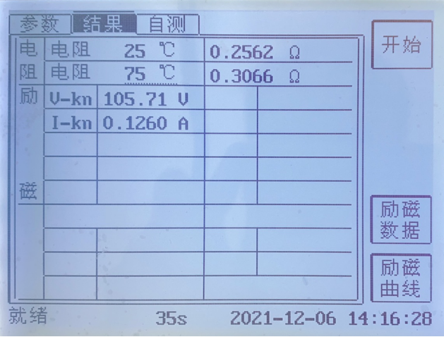

After the test is completed, print the excitation data and volt-ampere characteristic curve. Compare the obtained excitation data, knee voltage and knee current with the factory excitation data of the transformer. Generally, if the knee voltage is higher than the product of the secondary voltage and the corresponding winding ratio, the PT can be judged as qualified.
24-hours hot line 400-099-8859 technical hot line: 13971234137

Copyright © 2024 All rights Reserved.
备案号:鄂ICP备05010718号-1
