Contact: sales@haomai.net
NEWS
Company News
Principle and Method for Commissioning Differential Protection with Two-phase Current Method
The commissioning of transformer differential protection is relatively common in relay protection tests. It is convenient to commission differential protection with a six-phase relay protection tester, which avoids wiring problems and current compensation problems. Then, how to commission differential protection with only two-phase current? This paper introduces the commissioning of NR Electric PCS-978 differential protection using the Relaystar-Z70 Handheld Relay Protection Tester.

△ Relaystar-Z70 Handheld Relay Protection Tester
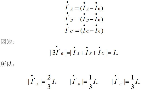
The relay protection tester only provides two-phase current, and only single-phase or two-phase current is injected into each side for verification. When conducting Y/Y verification for the high-to-medium voltage side, inject a current I∗ into phase A of either side. The conversion formula of the protection device is as follows:
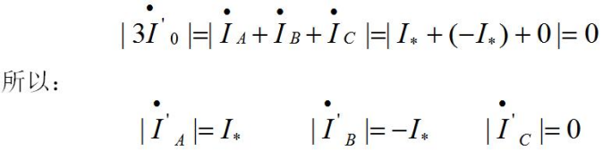
That is, both phases B and C will be affected. To avoid this impact and facilitate the verification, the wiring method adopted for the high and medium voltage sides is as follows: the current flows through phase IA of the Relaystar-Z70, entering from phase A of the high voltage side and exiting from phase B. The wiring method for the medium voltage side is as follows: the current flows through phase IC of the Relaystar-Z70, entering from phase A of the medium voltage side and exiting from phase B.

△ Wiring Diagram for High-to-medium Voltage Differential Protection
The phase angle difference of the current injected into the high and medium voltage sides is 180°, and the magnitude is I∗ (where I∗ refers to the secondary rated current of the two sides). Phase IA of the Relaystar-Z70 outputs the rated current of the high voltage side with a phase of 0°, and phase IC outputs the rated current of the medium voltage side with a phase of 180°, so there should be no differential current in the device. It is only necessary to change the current amplitude of either side to generate differential current, and the differential protection will operate when the differential current value reaches the differential operation threshold.
When conducting Y/Δ verification for the high-to-low voltage side, the wiring method for the high voltage side is as follows: the current flows through phase IA of the Relaystar-Z70, entering from phase A of the high voltage side and exiting from phase B. The wiring method for the low voltage side is as follows: the current flows through phase IC of the Relaystar-Z70, entering from phase A of the low voltage side and exiting from phase A.

△ Wiring Diagram for High-to-low Voltage Differential Protection
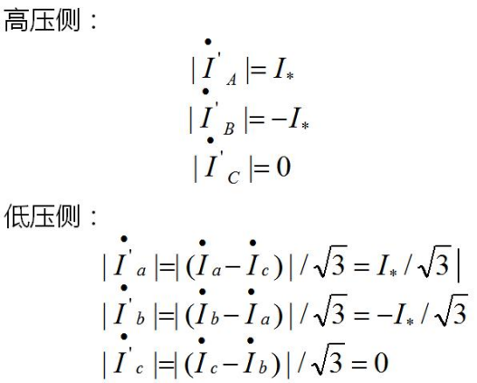
It can thus be concluded that the phase angle difference of the currents injected into the high and low voltage sides is 180∘, with the magnitude of Side I being I∗ and that of Side II being √3 I∗ (where I∗refers to the secondary rated current of both sides).Specifically, phase IA of the Relaystar-Z70 outputs the rated current of the high voltage side with a phase of 0∘, and phase IC outputs √3 times the rated current of the low voltage side with a phase of 180∘. Under this condition, the protection device should have no differential current.Simply changing the current amplitude of either side will generate a differential current, and the differential protection will operate when the differential current reaches the operation threshold.
When verifying the slope of the percentage differential protection, gradually reduce the output current value of the high (low) voltage side until the differential protection operates, and record the current values of the two sides at the time of operation—these values are the operation boundary values. Then amplify (reduce) the current values by N times simultaneously, starting from the balanced state until the differential protection operates again, and record the current values of the two sides at this time. Calculate the slope of the percentage boundary using these two sets of data, and determine whether the two selected points are within the same slope segment according to the range of the restraint current value. This method requires partial calculations, which can further help understand the operating principle of differential protection, and realize the commissioning of differential protection with two-phase current from the relay protection tester.
24-hours hot line 400-099-8859 technical hot line: 13971234137

Copyright © 2024 All rights Reserved.
备案号:鄂ICP备05010718号-1
