Contact: sales@haomai.net
NEWS
Company News
Technical Practice | Commissioning Method for Generator-transformer Unit Differential Protection
Protection Device: PCS-985 Generator-transformer Unit Protection Device
Test Instrument: Relaystar-7000 Digital-analog Integrated Relay Protection Tester
The diagram below shows the generator-transformer unit system of a power plant. The main transformer is a three-winding transformer, and the low-voltage side of the station transformer has a double-branch structure. The generator-transformer unit differential protection includes four branch currents, namely the 220kV side current I1, 110kV side current I2, high-voltage station transformer high-voltage side current I3 and generator neutral point side current I4 of the main transformer. The polarity terminals of TA on each side are shown in the figure, and the reference direction of each side current is defined as positive when flowing into the generator-transformer unit.

△ Generator-transformer Unit System Diagram

△ Differential Operating Characteristic Diagram
Percentage Differential Protection Operating Equation:

This paper introduces how to use the Relaystar-7000 Digital-analog Integrated Relay Protection Tester to commission the PCS-985 generator-transformer unit differential protection.
01 Protection-related Settings
- Protection Setting Value and Control Word Configuration
|
Serial Number |
Setting Name |
Value |
Serial Number |
Setting Name |
Value |
|
01 |
Rated Capacity of Main Transformer |
360MVA |
09 |
Secondary Side of Generator TA |
5A |
|
02 |
Primary Rated Voltage of High-voltage Side |
242kV |
10 |
- |
- |
|
03 |
Primary Side of High-voltage Side TA |
1250A |
11 |
Generator-transformer Unit Differential Pickup Value |
0.4Ie |
|
04 |
Secondary Side of High-voltage Side TA |
1A |
12 |
Generator-transformer Unit Differential Instantaneous Value |
5Ie |
|
05 |
Rated Capacity of Generator |
330MVA |
13 |
Initial Slope of Percentage Restraint |
0.1 |
|
06 |
Power Factor of Generator |
0.94 |
14 |
Maximum Slope of Percentage Restraint |
0.7 |
|
07 |
Primary Rated Voltage |
20kV |
15 |
Differential Instantaneous Protection Enable |
1 |
|
08 |
Primary Side of Generator TA |
15000A |
16 |
Percentage Differential Protection Enable |
1 |
- Protection Press Plate Configuration
In the "Press Plate Settings", set the "Generator-transformer Unit Differential Protection" soft press plate to "1", set the "Maintenance" hard press plate to "1", and disconnect the "Trip Output" hard press plate.
02 Test Wiring
The YD11 current phase compensation of the generator-transformer unit differential protection in the PCS-985 device adopts the method of compensation from the Y side to the Δ side:
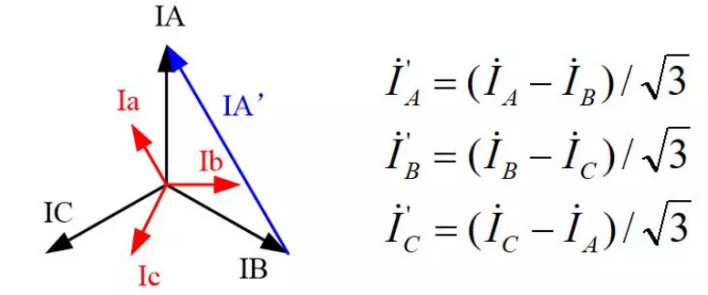
△ PCS-985 Phase Conversion Vector Diagram and Formula
For the YD-11 main transformer connection mode, the PCS-985 device adopts the method of phase correction from the main transformer high-voltage side currents A-B, B-C, C-A to the generator neutral point side. During the differential protection test, currents are injected from the high-voltage side and the generator neutral point side respectively.
The corresponding relationship of the injected currents between the high-voltage side and the neutral point side is: A - ac, B - ba, C - cb.
When a current IA= ∠0∘, IB=0, IC=0 is injected into the high-voltage side, the converted currents are IA′=1∠0∘, IB′=0, IC′=1∠180∘.The corresponding currents injected into the low-voltage side are Ia=1∠180∘, Ib=0, Ic=1∠0∘.
∘.
△ PCS-985 Differential Wiring Diagram
03 Test Method
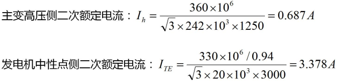
- Calculate the Secondary Rated Current of Each Side
- Inject Balancing Current
According to the above test wiring and analysis, the two-phase current output of the Relaystar-7000 can be used to inject the generator-transformer unit differential balancing current. Apply a current IA=1.732×0.687=1.19A∠0∘ to phase A on the high-voltage side, inject a current IB=3.378A∠180∘ into phase A on the neutral point side, and output a current of 3.378A∠180∘ from phase C on the neutral point side. After applying the currents in accordance with the above settings, check the protection sampling data: the generator-transformer unit differential current is 0Ie, and the restraint current is 1Ie.

△ Generator-transformer Unit Balancing Current Parameter Settings
Percentage Differential Boundary TestConduct the test according to the table below. Note that the high-voltage side current needs to be divided by 1.732 when converted to the rated current during the test. The test data are shown in the table below.
|
Serial Number |
Current on Side 1 (A) |
Current on Side 2 (A) |
Restraint Current Ir (A) |
Differential Current Id (A) |
|
A |
Ie |
Ie |
Ie |
Ie |
|
1 |
1.19 |
1 |
1.689 |
0.5 |
|
2 |
1.87 |
1.57 |
3.378 |
1 |
|
3 |
3.4 |
2.85 |
6.756 |
2 |
|
4 |
5.13 |
4.31 |
10.134 |
3 |
|
5 |
7.12 |
5.98 |
13.512 |
4 |
|
6 |
9.41 |
7.98 |
16.89 |
5 |
04 Test Conclusion
Based on the restraint current Ir and differential current Id from the above test data, the generator-transformer unit differential percentage boundary curve can be plotted.

24-hours hot line 400-099-8859 technical hot line: 13971234137

Copyright © 2024 All rights Reserved.
备案号:鄂ICP备05010718号-1
