Contact: sales@haomai.net
NEWS
Company News
Case Practice | Charging Module Characteristic Test of Substation DC System
Test Item: Charging Module Characteristic Test of 220kV Substation DC System
Test Equipment: FDT-220/110 DC System Comprehensive Tester
DC System Voltage: 220V
Charging Module: 220V/20A
Storage Battery: 2V/104 Cells/400Ah

1 Pre-test Preparation
- Transfer the load to avoid power loss of the DC busbar.
- Isolate the module under test and prohibit simultaneous testing of multiple modules.
- Take adequate safety measures and strictly comply with relevant regulations.
- Arrange special personnel for supervision, and place the equipment in a well-ventilated area to prevent heat accumulation.
2 Test Wiring
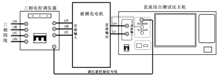
△ Wiring Schematic Diagram

△ On-site Wiring Diagram
The three-phase electronic voltage regulator is connected in series between the three-phase four-wire power supply and the input of the charger under test. The output of the voltage regulator is connected to the input of the charger under test, and the control signal line of the voltage regulator is connected between the voltage regulator and the host to realize the host's automatic control of the voltage regulator. The DC output of the charger is connected to the current loop and voltage loop of the host respectively.
3 Software Operation

Click Charger Characteristic Test on the main interface to configure the charger parameters. Set the substation number, charger number and module number according to the on-site conditions. Set the constant current setting value and rated voltage according to the actual parameters of the charging module.
Since a voltage regulator is connected in this test, check the option Use Voltage Regulator. During the voltage regulation accuracy and current regulation accuracy tests, the device will automatically adjust the AC input voltage to 85%, 100% and 115% of the rated AC input voltage.
When Voltage Regulation Accuracy Test is checked, three current points need to be set, with values ranging from 0–100% of the rated output current of the charging module. This means the charging module will output three set current values under the condition of constant voltage. In this test, according to on-site requirements, the values are set to 30, 60 and 90.
When Current Regulation Accuracy Test is checked, three voltage points need to be set, with values ranging from 80–95% of the rated output voltage of the charging module. This means the charging module will output three set voltage values under the condition of constant current. The test can be performed with the default parameters of 95, 90 and 80.
4 Test Result Analysis
Voltage Regulation Accuracy Test

The load current refers to the three current points set previously, the AC voltage refers to the output value of the voltage regulator, and the DC voltage refers to the DC voltage output under corresponding conditions. The tester automatically calculates the voltage regulation accuracy based on the measured data.
Voltage Regulation Accuracy Calculation Formula: δU =(Um-Uz)/Uz×100%
δU: Voltage regulation accuracy
Um: Limit value of output voltage fluctuation
Uz: Test value of output voltage
Voltage Regulation Accuracy Requirements:
- Phase-controlled type: ≤±1%
- High-frequency switching type: ≤±0.5%; Setting error ΔU=(Uz−Un)/Uz, not exceeding ±0.5%
Test Conclusion: The voltage regulation accuracy of the charging module meets the requirements.
Current Regulation Accuracy Test

The DC voltage refers to the three voltage points set previously, the AC voltage refers to the output value of the voltage regulator, and the load current refers to the current value output under corresponding conditions. The tester automatically calculates the current regulation accuracy based on the measured data.
Current Regulation Accuracy Calculation Formula: δI=(Im-Iz)/Iz×100%
δI: Current regulation accuracy
Im: Limit value of output current fluctuation
Iz: Test value of output current
Current Regulation Accuracy Requirements:
- Phase-controlled type: ≤±2%
- High-frequency switching type: ≤±1%; Setting error ΔI=(Iz−In): not exceeding ±0.3A (below 30A)
Test Conclusion: The current regulation accuracy of the charging module meets the requirements.
24-hours hot line 400-099-8859 technical hot line: 13971234137

Copyright © 2024 All rights Reserved.
备案号:鄂ICP备05010718号-1
