Contact: sales@haomai.net
NEWS
Company News
Case Practice | Commissioning Method for Generator-transformer Unit Overexcitation Protection
Overexcitation protection is designed to prevent damage to generators and transformers caused by overexcitation. Derived from the formula for the induced electromotive force E of transformer windings E=4.44NfΦ, when the winding is supplied with rated voltage, the voltage U is balanced with the electromotive force E, meaning the voltage and electromotive force are essentially equal (the leakage impedance of the transformer is very small, resulting in a negligible voltage drop caused by leakage impedance).
For the same winding, with 4.44N held constant and voltage frequency unchanged (i.e., f remains stable), only the magnetic flux Φ varies with voltage changes. Under normal operating conditions corresponding to the rated voltage, the magnetic flux in the iron core brings the transformer core into a semi-saturated state, and this magnetic flux is defined as the rated magnetic flux. The magnetic flux Φ is generated by the magnetizing component of the current flowing through the transformer winding, which is referred to as the normal magnetizing current component. If the voltage applied to the transformer winding exceeds the rated voltage, the magnetizing current component must increase to maintain the balance between electromotive force and voltage, putting the transformer into an overexcitation state. Overexcitation causes core saturation and increased power loss, which in turn raises the heat generation of the winding. Excessive overvoltage relative to the rated voltage will lead to severe overexcitation, and the transformer may even burn out due to overheating.
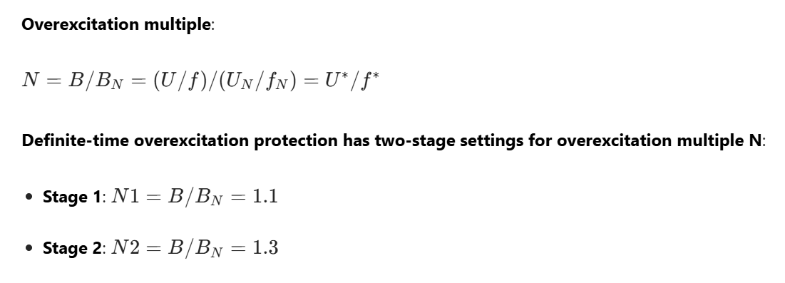
Generally, Stage I protection operates with a time delay to issue a signal and reduce the excitation current of the generator-transformer unit. Stage II protection generally operates to trip the unit, de-excite the generator, and execute programmed tripping. When a shared overexcitation protection device is used for both the generator and the transformer, the setting value is determined based on the component with lower overexcitation capability. The transformer overexcitation protection calculates the overexcitation level using the voltage and frequency of the high-voltage side, while the generator overexcitation protection uses the terminal voltage and frequency of the generator. The overexcitation protection is automatically blocked when a TV (voltage transformer) circuit fault occurs. To eliminate the impact of voltage transients from the high-voltage side TV, the transformer overexcitation protection is blocked by the no-current condition on either the high-voltage side or the low-voltage side (neutral point) of the transformer.
In this test, the Relaystar-1600S Relay Protection Tester was used to complete the overexcitation protection test of the generator with the RCS-985 Generator-transformer Unit Protection Device.

△ Relaystar-1600S Relay Protection Tester
1.Test Wiring

2. Protection Setting Values and Control Word Configuration
|
Setting Name |
Value |
Setting Name |
Value |
|
Overexcitation Protection Enable |
1 |
Transformer Overexcitation Protection Enable |
1 |
|
Overexcitation Stage I Setting Value |
1.31 |
Overexcitation Stage I Time Delay |
0.5s |
|
Overexcitation Stage I Trip Control Word |
1E3B |
|
|
3. Test Method
Based on the overexcitation calculation formula, there are two methods to adjust the overexcitation multiple: voltage boosting and frequency reduction. Both methods were adopted in this overexcitation protection test.
1) Voltage Boosting Method
According to the overexcitation multiple formula, to achieve 1.05 times the overexcitation setting value while keeping the frequency constant, the test voltage needs to be set to 79.5V.
Note: To avoid the impact of voltage transients, the transformer overexcitation protection is blocked by the no-current condition on the high and low-voltage sides of the transformer.The state sequence settings are as follows:
State 1:

State 2:

2) Frequency Reduction Method
Calculated from the formula, to meet the overexcitation multiple at the rated voltage, the test frequency should be set to 38.16Hz.
The state sequence settings are as follows:
State 1:

State 2:

4. Test Results and Conclusions

Based on the overexcitation protection principle and the test process, special attention should be paid to the overexcitation capacity of primary equipment and its matching with the overexcitation protection device, so as to avoid unnecessary accidents during operation.
24-hours hot line 400-099-8859 technical hot line: 13971234137

Copyright © 2024 All rights Reserved.
备案号:鄂ICP备05010718号-1
