Contact: sales@haomai.net
NEWS
Company News
Case Practice | Curve Search Commissioning Method for Electric Railway Differential Protection
Enterprise News
Case Practice | Curve Search Commissioning Method for Electric Railway Differential Protection
Release Date: November 28, 2023 Wuhan Haomai Electric Power Automation Co., Ltd.
Protection Device: WBH-892 Main Transformer Protection Device
Test Equipment: Relaystar-1600 Relay Protection Tester

△ Relaystar-1600 Relay Protection Tester
The WBH-892 Main Transformer Protection Device is applicable to AC electrified railway traction substations, serving as the main and backup protection device for traction main transformers. The following describes how to use the dedicated railway commissioning function of the Relaystar-1600 Relay Protection Tester to perform the differential ratio and differential boundary curve search commissioning for the three-phase V/V connection of the protection device.

△ Operating Characteristics of Ratio Differential Protection

1 Protection-related Settings
1) Protection Fixed Value Control Word Settings
|
Serial Number |
Fixed Value Name |
Value |
Serial Number |
Fixed Value Name |
Value |
|
01 |
Traction Transformer Connection Group |
Three-phase V/V |
12 |
Phase A Zone II Restraining Current |
1.09A |
|
02 |
High-voltage Side Rated Voltage |
110kV |
13 |
Phase B Differential Instantaneous Value |
6.04A |
|
03 |
High-voltage Side CT Primary Value |
400A |
14 |
Phase B Ratio Differential Current |
0.31A |
|
04 |
High-voltage Side CT Secondary Value |
1A |
15 |
Phase B Zone I Restraining Current |
0.62A |
|
05 |
Low-voltage Side Phase a CT Primary Value |
1000A |
16 |
Phase B Zone II Restraining Current |
1.88A |
|
06 |
Low-voltage Side Phase a CT Secondary Value |
1A |
17 |
Phase C Differential Instantaneous Value |
3.49A |
|
07 |
Low-voltage Side Phase b CT Primary Value |
1000A |
18 |
Phase C Ratio Differential Current |
0.18A |
|
08 |
Low-voltage Side Phase b CT Secondary Value |
1A |
19 |
Phase C Zone I Restraining Current |
0.36A |
|
09 |
Phase A Differential Instantaneous Value |
3.49A |
20 |
Phase C Zone II Restraining Current |
1.09A |
|
10 |
Phase A Ratio Differential Current |
0.18A |
21 |
Zone I Restraining Ratio |
0.30 |
|
11 |
Phase A Zone I Restraining Current |
0.36A |
22 |
Zone II Restraining Ratio |
0.50 |
|
- |
- |
- |
23 |
Differential Instantaneous Protection |
1 |
|
- |
- |
- |
24 |
Differential Protection |
1 |
2) Protection Press Plate Settings
In the Press Plate Fixed Value menu, set the Differential Protection soft press plate to "1", set the Maintenance hard press plate to "1", and open the Trip Output hard press plate.
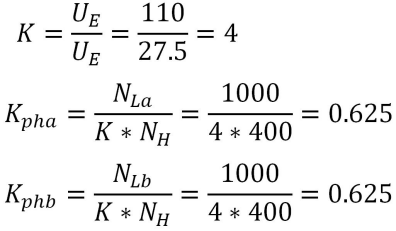
3) Calculate the Balance Coefficient
According to the current balance coefficient calculation formula for V/V connection differential protection in the protection device manual, combined with the fixed values, the balance coefficient can be obtained as follows:
2 Test Wiring

- Relaystar-1600 Wiring

- Protection Panel Terminal Block Wiring


3 Test Method

Enter the dedicated test interface for electric railway differential protection curve search.

- Click Import Test Parameters, select the protection device template directly, click Open, and the template will be imported automatically (the template can be edited and saved during the test).

- After importing the template, check and confirm whether the parameter settings are correct.

Main Parameter Settings:
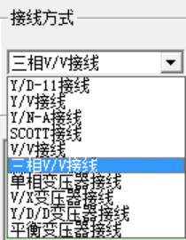
Wiring Mode: The Relaystar-1600 test software provides multiple wiring modes. Select the mode according to the actual wiring; the software will automatically associate the corresponding formulas after selection.
CT Polarity Selection for High and Low-voltage Sides: Options include one side pointing to the transformer and both sides pointing to the transformer. This device adopts the mode of one side pointing to the transformer.
Differential Instantaneous Value and Threshold Value: Set according to the protection fixed values.
Balance Coefficient Setting: Two methods are available: setting based on rated voltage and CT ratio, or direct input of the balance coefficient. If the balance coefficient has been calculated, it can be filled in directly.
Test Phase Selection: Differential curve search can be performed for phases A, B, and C respectively.

Inflection Point Setting: Check multiple inflection points and confirm the fixed values and slopes by referring to the setting sheet.
Initial Value and Final Value: Determine the range and step size of the curve search, which can be adjusted according to actual conditions or set to default values.
After checking and confirming the above parameters, add a sequence to start the test.
Note: Since the model parameter template is imported during the test, it is only necessary to check the fixed values of differential protection, restraining current and slope; no modification is required for other parameters, making the test process convenient and efficient.
4 Test Results
After starting the test, the test software can display the real-time current value and the actual differential current at each point. The differential dotting curve will be depicted in the graph on the right side. The test data is shown in the table below:
|
Serial Number |
Status |
Ir |
Set Id |
Actual Id |
Operation Time |
Conclusion |
|
1 |
★ |
0.500 A |
0.222 A |
0.227 A |
0.054 s |
Qualified |
|
2 |
★ |
1.500 A |
0.604 A |
0.609 A |
0.027 s |
Qualified |
|
3 |
★ |
2.500 A |
1.104 A |
1.109 A |
0.027 s |
Qualified |
|
4 |
★ |
3.500 A |
1.604 A |
1.609 A |
0.027 s |
Qualified |
|
5 |
★ |
4.500 A |
2.104 A |
2.109 A |
0.027 s |
Qualified |
|
6 |
★ |
5.500 A |
2.604 A |
2.609 A |
0.026 s |
Qualified |
|
7 |
★ |
6.500 A |
3.104 A |
3.109 A |
0.026 s |
Qualified |
|
8 |
★ |
7.500 A |
3.490 A |
3.484 A |
0.031 s |
Qualified |
|
9 |
★ |
8.500 A |
3.490 A |
3.484 A |
0.031 s |
Qualified |
Based on the above test data, the software automatically depicts the differential ratio restraining boundary curve.

The above operations complete the phase A differential curve test. For phase B and C tests, no rewiring is required; the test can be started only by setting the fixed values of phase B and C.
Note: Since the fixed values of each phase are different, phases B and C may operate during the phase A test, which will affect the accuracy of curve search. In this case, the fixed values of non-tested items can be increased to minimize their operation, or the trip matrix of non-tested items can be turned off, so that the tested phase curve will be more accurate.
24-hours hot line 400-099-8859 technical hot line: 13971234137

Copyright © 2024 All rights Reserved.
备案号:鄂ICP备05010718号-1
