Contact: sales@haomai.net
NEWS
Company News
Case Practice | Bilateral Commissioning Test Method for Line Differential Protection
Enterprise News
Case Practice | Bilateral Commissioning Test Method for Line Differential Protection
Release Date: May 24, 2024 Wuhan Haomai Electric Power Automation Co., Ltd.
Protection Device: CSC-103 Line Protection Device
Test Equipment: Relaystar-Z70 Handheld Digital-analog Integrated Relay Protection Tester
Line differential protection serves as the main protection for transmission lines. To facilitate the integrated test with communication channels, the device is equipped with a remote loopback test function with channels.

△ Line Differential Protection Circuit Diagram
As shown in the diagram above, CSC-103 Line Protection Devices are installed at both terminals M and N. The protection devices are connected to communication terminal equipment via optical cables, and the optical transceivers on the protection side are mounted at the back of the protection devices.The device can adopt either a dedicated optical fiber or a multiplexed channel. When the number of fiber cores and transmission distance permit, the dedicated optical fiber is preferred as the transmission channel. When the power conditions are not satisfied, the multiplexed channel can be adopted.
This paper introduces how to use two Relaystar-Z70 Handheld Digital-analog Integrated Relay Protection Testers to achieve synchronous output via GPS remote time synchronization, so as to complete the bilateral commissioning test for line differential protection.
1. Protection-related Settings
1) Protection Fixed Value Control Word Settings (Terminal M Side)
|
Serial Number |
Fixed Value Name |
Value |
Serial Number |
Fixed Value Name |
Value |
|
01 |
CT Primary Rated Value |
1200A |
11 |
Pilot Differential Protection |
1 |
|
02 |
CT Secondary Rated Value |
1A |
12 |
CT Open-circuit Blocking Differential Protection |
0 |
|
03 |
PT Primary Rated Value |
220kV |
13 |
Internal Communication Clock |
1 |
|
04 |
CT Ratio Coefficient |
1 |
14 |
Single-phase Auto-reclosing |
1 |
|
05 |
Differential Current Startup Fixed Value |
0.1A |
15 |
Three-phase Auto-reclosing |
0 |
|
06 |
Zero-sequence Startup Current Fixed Value |
0.2A |
16 |
Auto-reclosing Forbidden |
0 |
|
07 |
Differential Operating Current Fixed Value |
1A |
17 |
Auto-reclosing Lockout |
0 |
|
08 |
Local Side Identification Code |
101 |
- |
- |
- |
|
09 |
Remote Side Identification Code |
102 |
- |
- |
- |
|
10 |
Single-phase Auto-reclosing Time |
0.8s |
- |
- |
- |
Note: For the N side terminal, the local side identification code is 102 and the remote side identification code is 101; other fixed values and control words are consistent with those of the M side terminal.
2) Protection Press Plate Settings
At both the M side terminal and N side terminal, set the Differential Protection soft press plate to "1" in the "Press Plate Fixed Value" menu. On the protection panel, put into service the Differential Protection function hard press plate and the Maintenance function hard press plate, and open the Trip Output hard press plate. Check that the optical fiber channel status of the protection device is normal (no channel abnormality alarm indication or message).
- Test Wiring
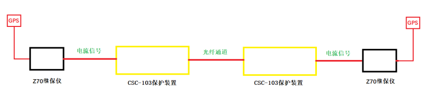
△ Line Differential Protection Wiring Diagram
This test requires two Relaystar-Z70 Handheld Digital-analog Integrated Relay Protection Testers with GPS time synchronization function. At the M side terminal, connect one Relaystar-Z70 to GPS for time synchronization and output current signals to the CSC-103 protection device. At the N side terminal, connect the other Relaystar-Z70 to GPS for time synchronization and output current signals to the CSC-103 protection device. The protection devices at both terminals are connected via optical fiber channels.
3. Line Differential Protection Test Method
Assign operators at both the M and N side terminals respectively. Configure the Relaystar-Z70 for GPS time synchronization, connect the GPS antenna properly, and confirm that the time synchronization is successful as displayed on the tester.

△ GPS Setting Method
1) Test Parameter Settings
Enter the State Sequence Test module for parameter configuration, simulating the test conditions from the normal load current state at both sides, to the fault state, and then to the auto-reclosing state.
State 1: Normal State Settings are shown in the figures below:

△ M Side Normal State Parameter Settings

△ N Side Normal State Parameter Settings
State 2: Fault State Settings are shown in the figures below:

△ M Side Fault State Parameter Settings

△ N Side Fault State Parameter Settings
State 3: Auto-reclosing State Settings are shown in the figure below:

△ M/N Side Auto-reclosing State Parameter Settings
2) Start the Test
Set the same start time point for both terminals. When the set time is reached, the testers at both ends start running simultaneously to achieve synchronous output according to the configured states.

△ Time Synchronization Setting
3) Test Results
In State 1, check the sampling values, differential current and restraining current at both terminals. In State 2, check the action messages at both terminals.

△ M Side State 1 Sampling Values

△ M Side Differential Current and Restraining Current Values

△ N Side State 1 Sampling Values

△ N Side Differential Current and Restraining Current Values

△ M Side Differential Protection Action and Auto-reclosing Action Messages

△ N Side Differential Protection Action and Auto-reclosing Action Messages
Analysis of the test results shows that:
When the current phases at both sides are in the same direction, the differential currents are summed and the restraining currents are subtracted.
When the current phases at both sides are in opposite directions, the differential currents are subtracted and the restraining currents are summed.
This fully complies with the operating logic of line differential protection. The differential protection does not operate when the differential current at both sides is less than the operating fixed value, and operates when the differential current exceeds the operating fixed value.
24-hours hot line 400-099-8859 technical hot line: 13971234137

Copyright © 2024 All rights Reserved.
备案号:鄂ICP备05010718号-1
