Contact: sales@haomai.net
NEWS
Company News
Case Practice | Primary Current Injection and Voltage Application Test for Large Power Transformers in 500kV Substations
Test Equipment: HTB-8000 New-type Test Device for Primary Current Injection and Voltage Application of Large Power Transformers (including 3 HTB-8000B Parallel Current Sources, 3 HTB-8000C Series Voltage Sources, and 3 Single-phase Voltage Regulators), Full Set of Test Wires
Given the excessively high equivalent short-circuit impedance of large power transformers, a new capacitive compensation method can be adopted. Capacitors are connected in series in the circuit to compensate for part of the inductive reactance, which reduces the impedance of the test circuit and increases the test current without changing the inductive effect of the test circuit (i.e., only under-compensation is applied during this process). Then, compensation capacitors are connected in parallel at both ends of the test power supply, achieving basically full compensation. For the test power supply, the entire circuit is close to a parallel resonance state. This compensated current injection method reduces the requirements for the system power supply while increasing the test current. The following describes the current injection test method for large power transformers.
1. Wiring Method
1) Wiring of Current Injection Test Device
Connect the single-phase voltage regulator, HTB-8000B and HTB-8000C in series to form the phase A output circuit. The same wiring method applies to phases B and C.The working power supply of the 3 single-phase autotransformers is AC 380V (the air switch shall be not less than 16A). The three phases use the live wires of phases A, B and C respectively, with a shared neutral wire (to ensure an output phase angle difference of 120°).The HTB-8000B is connected to a working power supply of AC 220V (10A). The HTB-8000B and HTB-8000C are connected via a shared aviation plug wire for power and communication. There is no other physical connection between each phase. The system output is connected to the current injection side of the transformer.
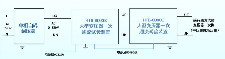
△ Phase A System Wiring Diagram (the same applies to phases B and C)
Single-phase Autotransformer: Serves as the high-power adjustable power supply input for the transformer current injection test.
HTB-8000B: Equipped with an independent control power supply (AC 220V) and a human-machine interface for operation; responsible for switching control of the parallel capacitor bank; acting as the core control system of the entire device.
HTB-8000C: Responsible for switching control of the series capacitor bank; equipped with an independent overvoltage and overcurrent protection system; forms the multiple overvoltage and overcurrent protection functions of the entire device together with the HTB-8000B.
2) Transformer-side Wiring
The figure below shows the primary interconnection wiring diagram of the capacity-expanded #2 main transformer.During the test, connect the output UT of the three-phase current injection test device to the medium-voltage side of the main transformer. Open the 221 switch, close the 2211 disconnecting switch, and open the 2211-1/2211-2 grounding switches. The current flows in from the P1 side of the CT as the high-current injection point.On the high-voltage side, close the 5012 disconnecting switch and the 501 switch, and close the 5011-1 grounding switch as the high-voltage side short-circuit point. This setup simulates current injection from the medium-voltage side to the high-voltage side.

△ Main Transformer Primary Main Wiring Diagram

△ On-site Test Device Wiring Diagram
3) On-site Safety Measures
All test devices must be reliably grounded.
Ensure no personnel are working in all areas where current is applied up to the short-circuit point.
The secondary side of all CTs in the current injection bay is not allowed to be open-circuited.
Assign personnel to be on duty in the relevant bays during the operation.
2. Test Procedure
Software Parameter Setting
Power on the HTB-8000B and enter the parameter setting interface. Set the parameters according to the transformer nameplate. Check that the rated voltage levels of the high, medium and low voltage sides are 505kV, 230kV and 36kV respectively, the transformer capacity is 1000MVA, and the short-circuit impedance between the high and medium voltage sides is 22.16%.

△ Transformer Nameplate
Set the short-circuit impedance multiple, rated capacity and rated voltage according to the nameplate. Calculate the short-circuit impedance value of the high-voltage side:Z=1000230×230×22.16%=11.72ΩThe voltage required when the output current reaches the upper limit of 100A is approximately 1172V.

△ Parameter Setting
After completing the parameter settings, the test can be started. Perform device self-test as prompted. When prompted to boost voltage, manually adjust the voltage regulator until the output reaches the required current value.
In the output values:
Voltage: The voltage applied to the transformer.
Current: The current in the circuit.
Phase Difference: The phase angle difference between voltage and current. A larger phase difference angle (φ) indicates that more reactive power needs to be compensated by the capacitor (cosφ), while the consumed active power is smaller (sinφ).
Input Value: The voltage and current values of the consumed active power.

△ Current and Voltage Values Applied by the Test Device
3. Test Conclusion
- Theoretical Calculation ValuesThe turns ratio of both the high-voltage side and medium-voltage side of this transformer is 4000:1. When a current of 100A is applied to the medium-voltage side, the calculated current of the high-voltage side is:I=100×505230=45.54AThen, the secondary current of the high-voltage side is:Ih=400045.54=0.011AThe secondary current of the medium-voltage side is:Im=4000100=0.025ASince the short-circuit point is outside the protection zone, the theoretical value of the transformer differential current should be 0.
- The secondary side current values measured by the YD-300 Wireless Telemetry Voltmeter-Ammeter Phase Meter are consistent with the calculated current values.
- Check the secondary current values on the protection and control device.

△ Transformer Protection Set A Sampling Values

△ Transformer Protection Set B Sampling Values
- Check the differential current values on the protection device.

△ Transformer Protection Set A Differential Current Values

△ Transformer Protection Set B Differential Current Values
- Analysis of the above data and comparison with the theoretical calculation values fully verify the reliability and accuracy of this test method, which meets the requirements of the primary current injection test for large transformers.
The HTB-8000 New-type Test Device for Primary Current Injection and Voltage Application of Large Power Transformers has a maximum input power of 2kW, an output voltage of 1300V, an output current of 100A, and a maximum capacity of 130kVA. Its design can meet the requirements of current injection tests for all bays through the transformer in the entire substation. The current injection bay applied is only related to the short-circuit point, which solves the problem that traditional current sources cannot perform primary current injection from transformers. It can complete bushing CT polarity verification, transformer differential and bus differential tests, and perform no-load current injection tests before power transmission to complete secondary current circuit inspection, which greatly improves the one-time power transmission success rate.
24-hours hot line 400-099-8859 technical hot line: 13971234137

Copyright © 2024 All rights Reserved.
备案号:鄂ICP备05010718号-1
