Contact: sales@haomai.net
NEWS
Company News
Case Practice | Load Simulation-based Relay Protection Vector Check for a Newly-built 1000kV Substation
During the construction and renovation of substations, polarity testing must be conducted after the installation of CTs and PTs to ensure their normal operation following power transmission. For transformers with high impedance (e.g., 1000kV ultra-high voltage transformers), Wuhan Haomai proposed a new capacitance compensation method and developed the HTB-8000 Large Transformer Primary Current Injection Test Device. This device can significantly increase the output test current and power while requiring only a low-capacity test power supply, enabling high-current primary-side injection tests on large transformers. It can conduct current injection tests across both sides of the transformer (with the opposite side short-circuited) and perform combined voltage and current injection tests on the primary circuits of both transformer sides.

1 Test Principle
- Load Simulation-based Relay Protection Vector Check Solution: Due to the excessively high equivalent short-circuit impedance of large power transformers, capacitance compensation is adopted. Capacitors are connected in series in the circuit to offset part of the inductive reactance, thereby reducing the test circuit impedance and increasing the test current without altering the inductive characteristics of the circuit (i.e., only under-compensation is applied at this stage). Compensation capacitors are then connected in parallel at both ends of the test power supply to achieve near-full compensation. From the perspective of the test power supply, the entire circuit operates close to a parallel resonance state. This compensation-based current injection method increases the test current while reducing the requirement for the system power supply.
- Homologous Voltage and Current Application Method: The device generates three-phase power frequency voltage with defined amplitude and phase sequence. After voltage boosting, the voltage is applied to the device under test to produce current with fixed phase relationships. The test voltage and current are converted into secondary voltage and current by mutual inductors, which are then fed into the relay protection device to complete the protection vector check. This solution can be used for vector checks of main transformer bushing CTs; when verifying main transformer differential protection, the injected current can pass through the main transformer.
2 Test Preparation

△ Main Transformer Nameplate Parameters
The transformers tested in this project are three 1000MVA phase-splitting transformers, with the voltage levels of the high, medium, and low sides being 1000/√3kV, 525/√3kV, and 110kV respectively.
Current Injection Test Wiring: Connect a single-phase voltage regulator, HTB-8000B, and HTB-8000C in series to form the phase A output circuit. The same connection method applies to phases B and C.The three single-phase autotransformers are powered by AC 380V (with an air switch rated at no less than 16A). The three phases use the live wires of A, B, and C respectively, with a shared neutral wire (to ensure a 120° phase angle difference in output).
HTB-8000B is connected to an AC 220V (10A) working power supply. HTB-8000B and HTB-8000C are connected via an aviation plug cable that integrates power and communication functions. There is no other physical connection between the three phases, and the system output is connected to the current injection side of the transformer.
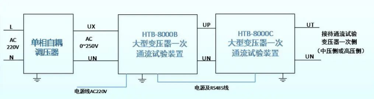
△ Phase A System Wiring Diagram (The same applies to phases B and C)
Single-phase Autotransformer: Serves as a high-power adjustable power supply input for the transformer current injection test.
HTB-8000B: Equipped with an independent control power supply (AC 220V) and a human-machine interface for operation. It controls the switching of parallel capacitor banks and acts as the core control system of the entire device.
HTB-8000C: Responsible for the switching control of series capacitor banks and features an independent overvoltage and overcurrent protection system. It collaborates with HTB-8000B to provide multiple overvoltage and overcurrent protection functions for the integrated device.
3 Test Process
During the on-site test, the transformer leads and earthing switches on the medium-voltage side were used as the output points of the test equipment. The high-voltage and low-voltage sides of the transformer were grounded separately to form a circuit. The impedance voltage, capacity, and other parameters of the corresponding transformer tap were input according to the transformer nameplate, and the device automatically calculated and configured the series and parallel compensation capacitors to achieve the optimal test effect.


After confirming that the grounding points were reliably connected and the transformer was set to tap position 5, the HTB-8000 injected current from the medium-voltage side and passed it through the relevant bays on the low-voltage side of the transformer. All safety and anti-misoperation measures were double-confirmed by the construction personnel and the person in charge.
The construction personnel operated the A, B, and C phases of the device, initiated the test, and synchronously adjusted the voltage regulator knob to control the input voltage applied by the device. A voltage of approximately 1300V and a current of 35A were applied to the medium-voltage side of the transformer, with stable output maintained for an extended period. The current flowed through the CTs of the medium-voltage side bays, passed through the transformer, and reached the CTs of the low-voltage side bays, completing the current injection for the CTs of the medium-low voltage side bays and the transformer bushing CTs. The vector verification of all protection devices on the low-voltage side was completed within 1 hour. Finally, the grounding points were switched to the high-voltage side to complete the inspection of the high-voltage side.


△ Low-voltage Side Protection Sampling Results
4 Result Analysis
The rated voltage of the medium-voltage side is 525/√3kV, and that of the low-voltage side is 110kV. When a current of 35A was applied to the medium-voltage side, the calculated current of the low-voltage winding was approximately 90A, which was consistent with the results displayed by the protection device. The sampling results from the background and other devices were all normal, and the phase-to-phase voltage of the low-voltage winding showed a positive sequence of 120°. The protection vector check for the low-voltage winding of the substation was thus successfully completed. The protection vector checks for the high-medium voltage windings of the transformer were completed using the same method.
The person in charge of the substation site stated that the device uses a capacitance compensation method, connecting capacitors in series in the circuit to offset part of the inductive reactance, thereby reducing the impedance of the test circuit. While increasing the test current, it significantly lowers the requirement for the system power supply. The overall performance of the device is stable, making it worthy of widespread promotion and application.
24-hours hot line 400-099-8859 technical hot line: 13971234137

Copyright © 2024 All rights Reserved.
备案号:鄂ICP备05010718号-1
