Contact: sales@haomai.net
NEWS
Company News
Case Practice | Battery Internal Resistance Testing and Activation Method
Battery Internal Resistance Testing Method
The DC power supply alarm system of a 110kV substation indicated a battery voltage fault. To quickly determine the battery status, the FR-3 Battery Internal Resistance Tester was used to measure battery voltage, internal resistance, battery capacity, and the resistance of connecting plates for analysis and judgment.
Long-press the power switch of the battery internal resistance tester to open the main interface, and select single-cell measurement, batch measurement, data processing, system settings, etc., as required. If the number of batteries to be tested is large, batch measurement can be selected.

The DC battery bank of this substation consists of 104 cells of 2V 200Ah lead-acid batteries. Open the parameter setting interface, set the voltage to 2V, battery type to 200Ah, station number to the work order number, battery bank number to 1, and number of battery cells to 104.

After completing the parameter settings, start the wiring. There are two wiring methods:

- Connect the black clip to the positive pole of the adjacent battery
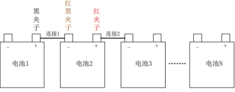
connect the black-red clip and the red clip to the negative pole of the battery under test.
- Connect the black clip and the black-red clip to the negative pole of the battery under test,connect the red clip to the positive pole of the battery under test.

After completing the wiring using either method, click Start Test. Judge the battery performance and connection status based on the measured voltage, resistance, battery capacity, and connecting plate resistance. The alarm was quickly identified as being caused by loose battery connecting plates, which led to excessively high circuit impedance. Immediate troubleshooting was performed to minimize the impact.
Battery Activation Method
The capacity of cells No.15 and No.16 among the 104-cell lead-acid battery bank of a substation failed to meet the specification requirements, with their voltages ranging from 1.95V to 2.00V. The HD-2612 Battery Single-cell Activator was adopted for activation in this case.

This battery single-cell activator is lightweight and portable. It adopts high-current cyclic charging and discharging technology to activate and maintain underperforming lead-acid batteries, and features three operating modes: discharge mode, charge mode, and activation mode. It is capable of charging, discharging, and activating 2V, 6V, and 12V single-cell batteries. During operation, it real-time monitors charging/discharging voltage, current, time, and dv/dt curves, and is equipped with an activation optimization setting function, ensuring high activation efficiency. The battery internal resistance can be measured for comparison after each activation cycle.
Operation Steps
- Remove the batteries to be activated from the battery bank, then perform activation on the single cells. Connect the red current clip to the positive terminal of the battery, and the black current clip to the negative terminal.

- Connect the red voltage clip to the positive terminal of the battery and the black voltage clip to the negative terminal, then turn on the power switch of the battery single-cell activator.
- Select Single-cell Activation on the main function interface to enter the parameter setting page.
- Press the confirm key to enter the voltage display interface. For the 2V 200Ah single-cell battery, set the voltage to 2V, then press confirm to enter the battery charging parameter setting interface.

- Set the equalizing charge voltage to 2.35V and the current to 0.1I₁₀A = 20A, click confirm to enter the battery activation curve display interface.
The interface displays the real-time voltage, current, and charging time of the battery. The activation will stop automatically when the battery is fully charged, and the cursor will stay at the "Start" position, indicating the completion of activation for cells No.15 and No.16.
Alternatively, cells No.15 and No.16 can be connected in series with one 2V 200Ah battery to form a 6V battery bank. Set the equalizing charge voltage to 7V and the current to 0.1I₁₀A, then start the activator for activation.
After 5 hours of activation using the HD-2612 Battery Single-cell Activator, the voltages of cells No.15 and No.16 recovered to the range of 2.10V–2.15V, meeting the commissioning requirements. The cells were then reconnected to the battery bank, restoring the normal operation of the system.
24-hours hot line 400-099-8859 technical hot line: 13971234137

Copyright © 2024 All rights Reserved.
备案号:鄂ICP备05010718号-1
