Contact: sales@haomai.net
NEWS
Company News
Common Problems and Solutions in Primary Current Injection and Voltage Application Tests for Large Substation Transformers
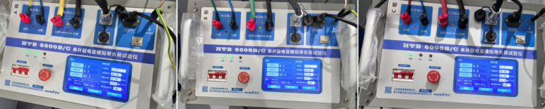
Test Equipment: HTB-8000 Large Transformer Primary Current Injection Test Device
Given the excessively high equivalent short-circuit impedance of large power transformers, a new capacitance compensation method is adopted. This compensation-based current injection method increases the test current while reducing the requirement for the input power of the test power supply.
1. Test Wiring
Wiring of the Current Injection Test Device
Connect phase A of the three-phase power supply to HTB-8000B and HTB-8000C, which are connected in series to form the phase A output. The same connection method applies to phases B and C.
HTB-8000B is connected to the working power supply of AC220V (10A). HTB-8000B and HTB-8000C are connected via an aviation plug cable that shares both power and communication functions. There is no other physical connection between each phase. The system output is connected to the current injection side of the transformer.
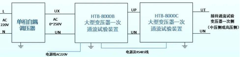
△ Phase A System Wiring Diagram (The same applies to phases B and C)
- HTB-8000B: Equipped with an independent control power supply (AC220V), a human-machine interface for operation, capacitor bank switching control, and serves as the core control system of the entire device.
- HTB-8000C: Responsible for capacitor bank switching control, with an independent overvoltage and overcurrent protection system. It collaborates with HTB-8000B to achieve multiple overvoltage and overcurrent protection functions.
2. Common Problems and Solutions During the Test
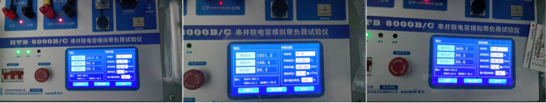
If an abnormality occurs during the test, first calculate the actual short-circuit impedance (output voltage divided by output current) when the device is operating, and compare it with the theoretical short-circuit impedance specified in the parameters to ensure correct parameter settings. The following describes common problems and their handling methods:
1) Output Voltage Available but No Output Current
During the voltage boosting and current injection process of the load-simulation test with current injected from the high-voltage side, current is output from phases A and B, but no current is output from phase C.
Cause: Phase C is not connected to the transformer circuit, resulting in failure of capacitance compensation for phase C and thus no current output. Locate the current injection point of phase C and the neutral (N) wire grounding point of phase C.
- Inspect the current injection point and find that the clip is not connected to the wire. Reconnect the clip and perform current injection again, but phase C still has no current output.

- Swap the output wires of phases B and C of HTB-8000C.

Phase B (actually phase C after swapping) has current output, while phase C (actually phase B after swapping) has no current output. It is judged that the current injection points of phases A, B, and C are normal, and the problem lies in the N wire grounding point.
③ Restore the output wires of phases B and C to their original positions, and swap the output N wires. Phase B now has no current output, while phase C has current output. It is concluded that the grounding point of the N wire clip of phase C connected to the ground bar is disconnected. The problem is resolved after replacing the grounding point.
2) Excessively High Input Current; Current Can Be Increased to Near the Preset Value but Cannot Reach It

Check the transformer tap position. According to the transformer nameplate, verify whether the reference voltage and short-circuit impedance values set for this tap position are correct. If the settings are correct, prioritize replacing the short-circuit point to eliminate primary circuit issues. Then, check whether the three N wires of the device are reliably grounded and whether the neutral point of the transformer is reliably grounded.
3) Confirmed Normal Circuit and Correct Parameter Settings, but Actual Short-circuit Impedance Is Inconsistent with Theoretical Short-circuit Impedance
In the case below, after completing the test on No.1 main transformer of a 220kV substation, the test was switched to No.2 main transformer only by changing the main transformer bay. However, current boosting failed. In addition, the medium-to-low voltage side of No.2 main transformer was normal, while the medium-to-high voltage side (with a theoretical short-circuit impedance of 14.09%) was abnormal.
Calculate the actual output short-circuit impedance to derive the short-circuit impedance parameter, and compare it with the nameplate parameter input into the device. Determine whether the actual value is higher or lower than the theoretical value, then take the average of the two values for adjustment. Repeat this process until the current reaches the preset value (e.g., the target value corresponding to the adjusted short-circuit impedance of 13.55%).
24-hours hot line 400-099-8859 technical hot line: 13971234137

Copyright © 2024 All rights Reserved.
备案号:鄂ICP备05010718号-1
