Contact: sales@haomai.net
NEWS
Company News
Case Analysis | On-Site Testing of Common Current Transformers in Substations
Location: A 110kV Substation of a State Grid Electric Power Company
Testing Equipment: CTP Series Transformer Tester
Test Object: Current Transformers (CT)
Test Items: DC Resistance, Excitation, Transformation Ratio
1 Test Wiring
Ground the CTP Series Transformer Tester; connect S1-S2 (source output) and M1-M2 (output measurement) to the protection winding of the secondary terminal box, and connect P1-P2 (induced voltage measurement) to the test phase on the primary side.
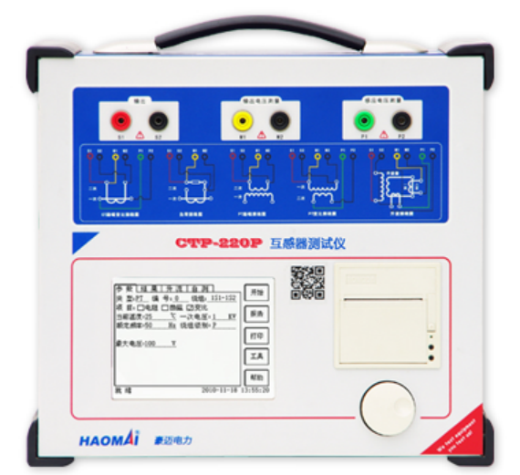
△ CTP Series Transformer Tester

△ Wiring Schematic Diagram

△ On-Site Wiring Diagram
2 Parameter Setting
- Set parameters according to the transformer nameplate.
- Click to start the test, and export the test report upon completion.
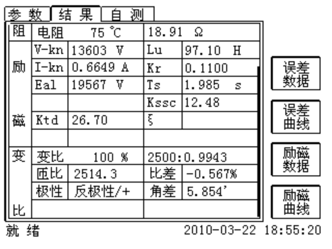
3 Error Analysis of Test Results
- Directly measure the impedance of the secondary circuit with the tester to obtain the circuit impedance value carried by the CT.
- Apply voltage from the secondary side to measure the DC resistance (converted to 75℃) and excitation curve of the CT secondary winding.
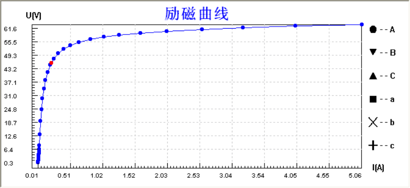
4 Calculation of Error Curve
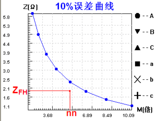
The tester automatically calculates the CT error curve based on the excitation curve and the DC resistance of the CT secondary winding. A 5% error curve is used for 5Pnn CTs, and a 10% error curve for 10Pnn CTs.
The horizontal axis of the error curve represents the maximum primary current of the CT (expressed as a multiple of the rated current), and the vertical axis represents the impedance value of the connected secondary circuit. The curve reflects the relationship between the maximum allowable multiple of the primary current and the impedance value of the connected circuit.
5 Analysis of Whether the CT Error Curve Meets the Requirements
For 5Pnn and 10Pnn CTs, the maximum current multiple can be regarded as nn, and the secondary circuit impedance as ZFH. Check the position of (nn, ZFH) on the curve: if it is below the curve, the CT meets the service requirements; if it is above the curve, the CT is unqualified.
6 Analysis of Whether the CT Accurate Limit Meets the Requirements
The tester can automatically calculate the accurate limit based on the given load and excitation curve.
Metering CT: Under the rated load, the ratio of the minimum primary current at which the composite error is equal to or greater than 10% to the rated primary current, depending on the accuracy class.
Steady-State Protection CT: The ratio of the rated accurate limit primary current to the rated current. Depending on the accuracy class, the accurate limit factor (ALF, Kalf) is defined as the primary current at which the composite error of the CT is less than or equal to 5% or 10%.
Transient Protection CT: The rated symmetrical short-circuit current multiple (Kssc) is the ratio of the rated primary short-circuit current (Ipsc, the root-mean-square value of the symmetrical primary short-circuit current) to the rated primary current.
7 Analysis of Whether the CT Error Limit Meets the Requirements
Metering CT - Ratio Error, Phase Error
The tester directly measures the CT turn ratio (the turn ratio is not necessarily an integer due to internal compensation measures of the CT). Calculate the ratio and phase error table under various currents and loads based on the excitation data. The ratio error and phase error increase with the decrease of the secondary current and decrease with the decrease of the secondary load. When the power factor of the secondary load increases, the ratio error decreases while the phase error increases.
According to the provisions of GB1208-2006 and DL/T866-2004, the error limits of metering CTs shall not exceed the values in the following table:
|
Accuracy Class |
Current Error, ±%(At the following percentages of rated current) |
Phase Difference(At the following percentages of rated current) |
||||||||||
|
±min (′) |
±crad |
|||||||||||
|
5% |
20% |
100% |
120% |
5% |
20% |
100% |
120% |
5% |
20% |
100% |
120% |
|
|
0.1 |
0.4 |
0.2 |
0.1 |
0.1 |
15 |
8 |
5 |
5 |
0.45 |
0.24 |
0.15 |
0.15 |
|
0.2 |
0.75 |
0.35 |
0.2 |
0.2 |
30 |
15 |
10 |
10 |
0.9 |
0.45 |
0.3 |
0.3 |
|
0.5 |
1.5 |
0.75 |
0.5 |
0.5 |
90 |
45 |
30 |
30 |
2.7 |
1.35 |
0.9 |
0.9 |
|
1 |
3 |
1.5 |
1 |
1 |
180 |
90 |
60 |
60 |
5.4 |
2.7 |
1.8 |
1.8 |
P-class, PR-class CT - Composite Error
During fault steady state, the primary current of tens of times the rated current will cause a large number of high-order harmonics in the CT secondary current; the smaller the high-order harmonics, the smaller the composite error. The tester automatically infers the composite error based on the excitation curve.
Composite Error: The maximum instantaneous error current during the specified duty cycle, expressed as a percentage of the peak value of the rated primary short-circuit current.
According to the provisions of GB1208-2006 and DL/T866-2004, the error limits of P-class and PR-class CTs shall not exceed the values in the following table:
|
Accuracy Class |
Current Error, ±%(At rated primary current) |
Phase Difference(At rated primary current) |
Composite Error, %(At rated accuracy limit primary current) |
|
|
±(′) |
±crad |
|||
|
5P(R) |
1 |
60 |
1.8 |
5 |
|
10P(R) |
3 |
— |
— |
10 |
TP-class Transient CT - Ratio Error, Phase Error, Peak Instantaneous Error
During fault transient state, the CT secondary current contains a decaying DC component.
Peak Instantaneous (Total) Error: The root-mean-square value of the difference between the instantaneous value of the primary current and the product of the instantaneous value of the secondary current and the transformation ratio (Kn) under steady-state conditions. The tester automatically calculates the peak instantaneous error based on the given load and excitation curve.
According to the provisions of GB16847-1997 and DL/T866-2004, the error limits of TP-class CTs shall not exceed the values in the following table:
|
Accuracy Class |
Current Error, ±%(At rated primary current) |
Phase Difference(At rated primary current) |
Maximum Peak Instantaneous Error, %(Under accuracy limit conditions) |
|
|
min(′) |
crad |
|||
|
TPX |
±0.5 |
±30 |
±0.9 |
Peak Instantaneous (Total) Error = 10% |
|
TPY |
±1 |
±60 |
±1.8 |
Peak Instantaneous (Total) Error = 10% |
|
TPZ |
±1 |
180±18 |
5.3±0.6 |
Peak Instantaneous AC Component Error = 10% |
24-hours hot line 400-099-8859 technical hot line: 13971234137

Copyright © 2024 All rights Reserved.
备案号:鄂ICP备05010718号-1
