Contact: sales@haomai.net
NEWS
Company News
How to Send FT3 Digital Quantities with a Relay Protection Tester
FT3 is a link layer transmission frame format specified in the IEC60044-8 protocol. When sending FT3 digital quantities with a relay protection tester, confirm the bay transformation ratio and name, and obtain the FT3 message information of the optical fiber channel through an optical digital signal analyzer, including logical nodes, data sets, logical devices, rated delay, bit rate, sampling rate and other parameters.
Test Equipment
Relaystar-7000 Integrated Digital Relay Protection Tester, NSA-60 Handheld Optical Digital Signal Analyzer

△ Relaystar-7000 Integrated Digital Relay Protection Tester

△ NSA-60 Handheld Optical Digital Signal Analyzer
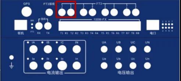
To simulate FT3 transmission with the Relaystar-7000, adjacent transmission channels must be used for FT3 simulation (in line with the communication logic of dual AD in digital quantities), and the FT3 transmission optical fiber should be connected to FT3 transmission port 1 or 2.
Power on the Relaystar-7000 and enter the main interface of the test system, click AC Test and configure the test parameters.

Click IEC61850 Settings and configure the communication parameters.

Communication Parameter Setting: Change the communication protocol to FT3 and set the FT3 communication data.
Set FT3 Channel 1, check TX1, set the number of sampling rate points and bit rate according to the communication data provided by the manufacturer of the device under test, and set LnNAME (logical node), DsName (data set), LdName (logical device) and delay time (rated delay) according to the data captured by the NSA-60 Handheld Optical Digital Signal Analyzer.

Set FT3 Channel 2, check TX2, and configure the same parameters as TX1.

Check both TX1 and TX2 at the same time, click Coefficient Setting, and confirm the corresponding mapping channel according to the provided data.

After the settings are completed, return to the AC test interface, the Relaystar-7000 completes the output, and check whether the FT3 sampling of the bay is displayed on the panel.
Troubleshooting if Sampling Cannot Be Displayed
Use the NSA-60 to capture the output packets of the Relaystar-7000:
If no message can be obtained, check the parameter settings of the Relaystar-7000.
If the message can be obtained, check whether the connected optical fiber is intact and the interface is connected correctly, and verify the bit rate and sampling rate of the device.
24-hours hot line 400-099-8859 technical hot line: 13971234137

Copyright © 2024 All rights Reserved.
备案号:鄂ICP备05010718号-1
