Contact: sales@haomai.net
NEWS
Company News
A Comprehensive Guide to Current Transformer (CT) Polarity Testing and Transformer Bushing CT Model Testing
Introduction
In the realm of power system commissioning and maintenance, ensuring the accuracy of protective relay schemes and metering systems hinges on two critical procedures: Current Transformer (CT) Polarity Testing and Transformer Bushing CT Model Testing. These tests validate the integrity of CT connections, phase relationships, and overall system reliability. This article explores their importance, methodologies, and real-world applications, with insights from a successful 220kV substation commissioning case in China.
Why CT Polarity Testing and Bushing CT Testing Matter
-
Preventing Catastrophic Failures
Incorrect CT polarity can lead to relay misoperation, false tripping, or failure to detect faults. For example, transformer differential protection relies on precise polarity alignment to compare currents entering and exiting the transformer. A single reversed CT connection could disable this critical safeguard. -
Ensuring Metering Accuracy
Revenue metering and load monitoring depend on accurate CT ratios and phase relationships. Errors in transformer bushing CT model testing may result in financial losses or grid instability. -
Compliance with Standards
Utilities must adhere to IEEE C57.13 and IEC 61869 standards, which mandate rigorous CT testing during substation commissioning.

Key Methodologies for CT Polarity and Bushing CT Testing
1. Current Transformer (CT) Polarity Testing
-
Primary Injection Method:
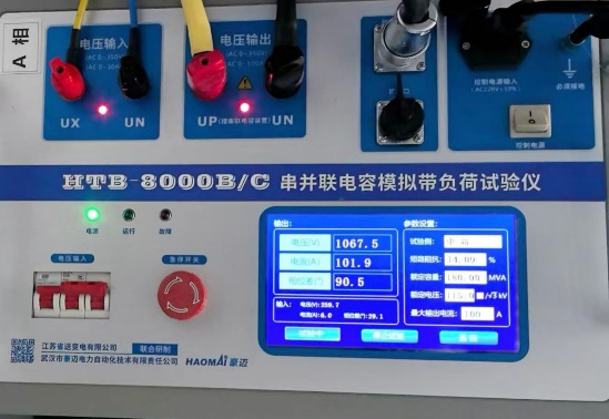
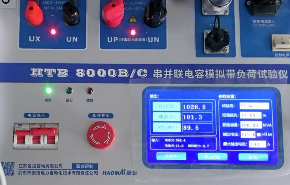
A high-current source (e.g., HTB-8000 test equipment) injects current through the CT primary winding. Secondary outputs are measured to verify polarity using a phase angle meter or relay test set.-
Advantage: Directly simulates real-load conditions.
-
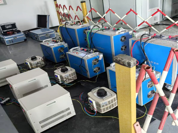
Case Study: At a 220kV substation in Jiangsu, China, HTB-8000 delivered 100A/1000V outputs, enabling simultaneous verification of multiple CTs across transformer windings in under 3 hours.
-
-
Secondary Voltage Method:
A low-voltage AC source is applied to the CT secondary, and the primary polarity is determined via induced voltage measurements.
2. Transformer Bushing CT Model Testing
-
Phase Relationship Verification:
Bushing CTs (installed on transformer bushings) must match the transformer’s vector group. Testing involves:-
Applying synchronized voltage and current (e.g., using YD-300E wireless-controlled sources) to simulate load flow.
-
Validating secondary outputs against expected phase angles.
-
-
Ratio and Burden Testing:
Ensure CTs meet rated ratios under actual burden conditions, critical for differential protection schemes.
Case Study: Revolutionizing Efficiency in a 220kV Substation
A newly built 220kV substation in Jiangsu, China, adopted an innovative CT polarity testing and transformer bushing CT model testing protocol, achieving remarkable results:
-
Streamlined Workflow
-
HTB-8000 High-Capacity Test System: Generated 100A current and 1000V voltage, covering all transformer windings (high, medium, and low voltage) in a single test cycle.
-
Wireless Control: YD-300E remote-controlled devices reduced manual intervention and enhanced safety.
-
-
Dual-Confirmation Safety Protocol
-
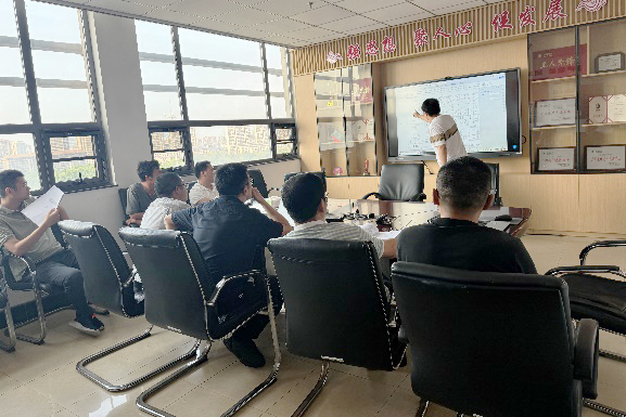
Construction and maintenance teams jointly verified safety measures (e.g., barriers, equipment status) and technical steps, minimizing human error.
-
-
Future-Proofing with Spare Circuit Validation
-
Spare feeder circuits were tested proactively, simplifying future expansions.
-
-
Results
-
50% Time Savings: Traditional methods requiring days were completed in hours.
-
Zero Operational Errors: All CT polarities and bushing CT phase relationships were confirmed accurate.
-
Best Practices for Effective Testing
-
Pre-Test Preparation
-
Review one-line diagrams and CT nameplate data.
-
Calculate injection currents to avoid overloading equipment.
-
-
Advanced Tools
-
Use multi-function test sets (e.g., HTB-8000) for combined voltage/current injection.
-
Deploy phase-angle meters with ±0.1° accuracy.
-
-
Documentation
-
Record test results in standardized templates for compliance audits.
-
Why This Approach is Gaining Global Traction
-
Cost Efficiency: Reduces downtime and labor costs.
-
Scalability: Adaptable to smart grids and renewable energy systems.
-
Safety: Eliminates risky live-line work during commissioning.
Conclusion
Current Transformer (CT) Polarity Testing and Transformer Bushing CT Model Testing are non-negotiable steps for ensuring grid reliability. By leveraging advanced equipment like the HTB-8000 and adopting standardized protocols, utilities can achieve faster, safer, and more accurate commissioning outcomes. The Jiangsu substation case exemplifies how these methods are transforming power systems worldwide—proving that precision today prevents disasters tomorrow.
Copyright © 2024 All rights Reserved.
备案号:鄂ICP备05010718号-1


