Contact: sales@haomai.net
NEWS
Company News
Test Method for Acceleration Protection After Reclosing
The reclosing test is a common test item for line protection. When a transient fault occurs on the line, the line can resume normal operation after the reclosing action; when a permanent fault occurs on the line, the circuit breaker will trip acceleratedly after the reclosing action. Taking the permanent fault of the RCS-931 Line Protection Device as an example, this paper introduces the verification method for acceleration after reclosing by using the integrated test module of the Relaystar-S60 Handheld Relay Protection Test System.
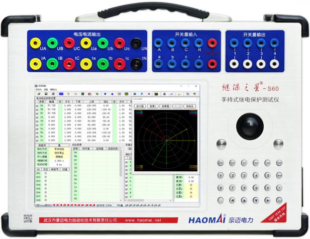
△ Relaystar-S60 Handheld Relay Protection Test System
1. Protection-Related Settings
(1) Protection Setting Configuration
|
Serial No. |
Setting Name |
Value |
Serial No. |
Setting Name |
Value |
|
01 |
Phase-to-Phase Distance Stage Ⅱ Setting |
4.0Ω |
03 |
Single-Phase Reclosing Time |
0.8s |
|
02 |
Phase-to-Phase Distance Stage Ⅱ Time |
0.5s |
04 |
Three-Phase Reclosing Time |
1.0s |
|
- |
- |
- |
05 |
Positive-Sequence Sensitive Angle |
79° |
(2) Protection Pressure Plate Setting
In the Setting Configuration menu, set the operation control words "Enable Phase-to-Phase Distance Stage Ⅱ", "Enable Three-Phase Reclosing" and "Internal Reclosing Switch" to 1 (1 = Enabled, 0 = Disabled), and set all other control words to 0.
In the Pressure Plate Setting menu, only set the "Enable Distance Protection Pressure Plate" to 1.
On the protection panel, only close the "Distance Protection" hard pressure plate.
- Test Wiring

△ RCS-931 Distance Protection and Reclosing Wiring Diagram
Connect the voltage output terminals Ua, Ub, Uc, Un of the Relaystar-S60 to the AC voltage terminals Ua, Ub, Uc, Un of the protection device respectively.
Connect the current output terminals Ia, Ib, Ic of the Relaystar-S60 to the polar terminals of the AC current terminals IA, IB, IC of the protection device respectively; short-circuit the non-polar terminals of the AC current terminals IA', IB', IC' of the protection device, then connect them to the polar terminal of the zero-sequence current (IN); finally, connect the non-polar terminal of the zero-sequence current (IN') back to the current output terminal In of the Relaystar-S60.
Connect the input contacts A, B, C, R of the Relaystar-S60 to the phase-separated tripping output contacts Trip A, Trip B, Trip C and the Reclosing contact of the protection device respectively; connect the +KM of the Relaystar-S60 to the common terminal of the protection device.
The switch position corresponding to the line is set to closed position, and the output wiring is not considered here.
3. Reclosing Function Verification
In the Integrated Test menu, the test process is controlled by the contact action status of the protection device. This test includes the following processes: Pre-fault → Fault (Tripping) → Normal State (Reclosing) → Fault (Accelerated Tripping).
- Parameter Setting on the Integrated Test Page

△ Test Parameter Setting
Integrated Test Parameters
- Fault Type: Simulate distance protection, set to phase-to-phase distance fault (AB phase short circuit).
- Setting Impedance: Set the amplitude to the Phase-to-Phase Distance Stage Ⅱ Setting (4.0Ω) and the phase angle to the Positive-Sequence Sensitive Angle (79.0°).
- Short-Circuit Impedance Multiple: Represents the position of the short-circuit point during the fault. According to the relay protection commissioning specification, it is generally set to 0.95 times to check the operation sensitivity of the protection device.
- Fault Current: Set the current during short circuit (generally ensure the calculated short-circuit voltage does not exceed the limit), which can be set to 5.0A.
- UX: No need to set UX when the setting value is not verified.
- Zero-Sequence Compensation Coefficient: Negligible here as the phase-to-phase distance protection is simulated.
- Conversion Fault: Not required here, uncheck the option.

△ System Parameter Setting
Integrated Test System Parameters
- Test Control Mode: Select Time Trigger for test convenience, and the time of each state is controlled by the Relaystar-S60.
Fault Duration: Time of the phase-to-phase fault, which shall be longer than the Stage Ⅱ setting time to ensure reliable operation.
Open State Time: Reclosing state time after the fault, which shall be longer than the reclosing setting time to ensure reliable reclosing action.
Reclosed Fault Time: Time of applying the test quantity for the permanent fault, to ensure continuous operation after reclosing.
- Fault Trigger Mode: Select Key Trigger (the trigger key is pressed after the protection reset time, including the reclosing charging time). The trigger can be started after observing the TV disconnection light off and charging light on of the protection device.
- Fault Nature: Set to Permanent Fault.
- PT Position: Generally installed on the bus side according to the actual situation; set the tripping mode to three-phase tripping.
- Fault Initial Angle: Lower than the setting synchronous closing angle (20°) to ensure reliable operation.
- Rated Voltage: Can be set to 57.735V (line voltage after tripping). The line voltage and bus voltage must be greater than 40V when verifying synchronization.
- Load Current: Set to 0 (no current output for the rated voltage output in the pre-fault state).
- Switch Delay: If testing with a simulated circuit breaker, it is recommended to set the tripping and closing delay to at least 0.020s.
(2) Test Operation Method
Start the test by clicking the right triangle button or pressing the "Run"/"Confirm" key on the keyboard, and the Relaystar-S60 starts outputting.
First output the no-load state (the normal state is output all the time before the key is pressed, waiting for the protection reset and the completion of reclosing charging).
Then output the fault state until the protection trips reliably and the input contacts A, B, C are all closed.
Next output the reclosing state until the protection recloses successfully and the input contact R is closed.
The test ends automatically finally; select whether to save the test results according to the prompt.
(3) Test Results
The input quantity records the test action information and reclosing information after the test. The protection action is shown in the figure below:

△ Protection Action Test Interface
Observe the protection action results and print the action report and action message, as shown in the table below:
Protected Equipment: Protection Device Version No.: V1.60 Print Time: 2019-12-13 19:38:29
|
Serial No. |
Start Time |
Relative Time |
Action Phase |
Action Element |
|
1072 |
2019-12-13 19:36:01:970 |
0000ms |
- |
Protection Start |
|
- |
- |
0526ms |
ABC |
Distance Stage Ⅱ Action |
|
- |
- |
1613ms |
- |
Reclosing Action |
|
- |
- |
1835ms |
ABC |
Distance Acceleration Action |
△ RCS-931 EHV Transmission Line Complete Protection Device — Integrated Action Report
24-hours hot line 400-099-8859 technical hot line: 13971234137

Copyright © 2024 All rights Reserved.
备案号:鄂ICP备05010718号-1
