Contact: sales@haomai.net
NEWS
Company News
Technical Practice | Commissioning Method for Directional Overcurrent Protection with Composite Voltage Blocking
Directional overcurrent protection with composite voltage blocking is a typical commissioning item for the high backup protection of main transformers. Due to the numerous blocking conditions, errors are prone to occur during the commissioning process. Taking the commissioning of the NR Electric PCS-978 main transformer protection with the Relaystar-S60 Handheld Relay Protection Test System as an example, this article introduces the specific commissioning method for directional overcurrent protection with composite voltage blocking.

△ Relaystar-S60 Handheld Relay Protection Test System
According to the logic block diagram of directional overcurrent protection with composite voltage blocking, in addition to meeting the requirements of relevant press plates, the protection will only operate when the voltage (OR gate relationship for low voltage and negative sequence voltage), direction and overcurrent conditions are satisfied with an AND gate relationship.
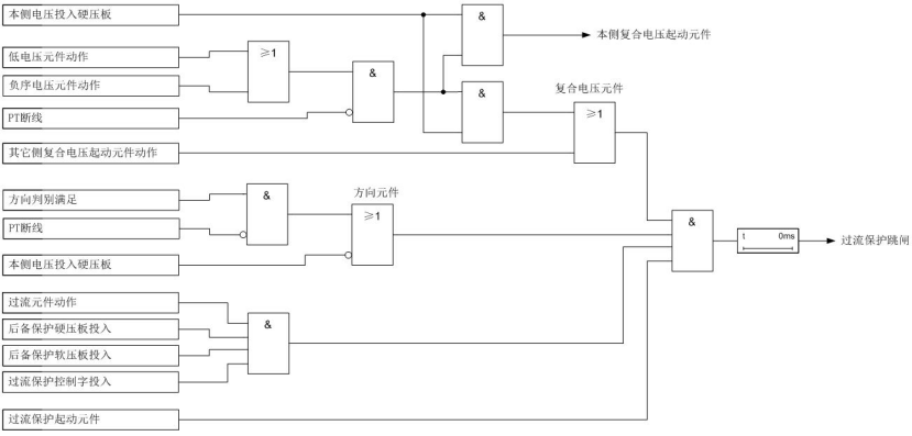
△ Logic Block Diagram of Directional Overcurrent Protection with Composite Voltage Blocking
Protection Control Words and Settings
|
No. |
Control Word |
Value |
No. |
Setting |
Value |
|
1 |
Overcurrent Zone I Enabled with Composite Voltage Blocking |
1 |
1 |
Low Voltage Blocking Setting |
70V |
|
2 |
Overcurrent Zone II Enabled with Composite Voltage Blocking |
0 |
2 |
Negative Sequence Voltage Blocking Setting |
6V |
|
3 |
Overcurrent Zone I Pointing to Bus |
0 |
3 |
Overcurrent Zone I Setting |
3A |
|
4 |
Overcurrent Zone I Time Delay 1 Enabled |
1 |
4 |
Overcurrent Zone I Time Delay 1 |
0.5s |
|
5 |
Overcurrent Zone I Time Delay 2 Enabled |
0 |
5 |
Overcurrent Zone I Time Delay 2 |
1.0s |
|
6 |
Overcurrent Zone II Enabled |
0 |
6 |
Overcurrent Zone II Setting |
2A |
|
|
|
|
7 |
Overcurrent Zone II Time Delay |
1.2s |
1. Verification of Directional Element
The directional element adopts positive sequence voltage with memory function, and has no dead zone for close-range three-phase short circuits. The wiring mode is zero-degree wiring. The sensitive angle is 45° when the direction points to the transformer, and 225° when the direction points to the power system. The figure below shows the action characteristics of the directional element, with the shaded area as the action zone.

a) Direction pointing to the transformer b) Direction pointing to the power system
△ Action Characteristics of Phase-to-Phase Directional Element
The AC test module is used for verification in this test. The control word "Overcurrent Zone I Pointing to Bus" is set to "0", indicating the direction points to the transformer with a sensitive angle of 45°. The test verifies the operation in the positive direction and non-operation in the reverse direction. Software settings for the normal state are configured before the test.

△ Initial State Parameter Setting
Start the operation after parameter setting to ensure the PT disconnection recovery and protection reset of the protection device, then check the changes of three-phase voltage and fault phase current.

△ Parameter Setting for Verifying Positive Direction Operation
Simulate a phase A ground fault with the IA fault phase angle set to 0°, and click the down arrow to enter the fault state within the action zone.

△ Action Value in Positive Direction Fault State
At this time, the low voltage and overcurrent value conditions are met, and the protection operates in the positive direction. Then set the IA phase current to 180° to verify non-operation in the reverse direction at the same time.
2. Verification of Composite Voltage
Composite voltage includes low voltage and negative sequence voltage, which need to be verified separately.
- Verification of Low Voltage Value
Set the normal state before the test to ensure the PT disconnection recovery and protection reset of the protection device, and first meet the overcurrent and direction conditions.

△ Low Voltage Blocking Parameter Setting
At this time, the protection is not released because the rated voltage is higher than the low voltage blocking setting value, then click the down arrow to enter the fault state.

△ Low Voltage Release Parameter Setting
At this time, the low voltage is 68.823V, which is lower than the setting value of 70V, the protection is released and the overcurrent protection operates. Then change the voltage step to 16V, and the low voltage becomes 70.555V which is higher than the setting value of 70V after the voltage drop, and the protection remains blocked.
- Verification of Negative Sequence Voltage Value
Set the normal state before the test to ensure the PT disconnection recovery and protection reset of the protection device, and first meet the overcurrent and direction conditions.

△ Negative Sequence Voltage Blocking Parameter Setting
At this time, the protection is not released because the negative sequence voltage is 0V which is lower than the negative sequence voltage blocking setting value, then click the down arrow to enter the fault state.

△ Negative Sequence Voltage Release Parameter Setting
At this time, the negative sequence voltage is 6.333V, which is higher than the setting value of 6V, the protection is released and the overcurrent protection operates. Then change the voltage step to 17V, and the negative sequence voltage becomes 5.667V which is lower than the setting value of 6V after the voltage drop, and the protection remains blocked.
3. Verification of Overcurrent Value
Set the normal state before the test to ensure the PT disconnection recovery and protection reset of the protection device, and first meet the composite voltage and direction conditions.

△ Overcurrent Blocking Parameter Setting
At this time, the protection is not released because the overcurrent value is 2.85A which is lower than the overcurrent setting value, then click the up arrow to enter the fault state.

△ Overcurrent Release Parameter Setting
The above methods verify the blocking and release conditions of the directional element, composite voltage (low voltage and negative sequence voltage) and overcurrent respectively. For specific setting verification, the variable step test can be set in the AC test interface. It should be noted that the step change time should not be too long, otherwise the protection will send out abnormal signals such as "CT Disconnection" or "PT Disconnection".
24-hours hot line 400-099-8859 technical hot line: 13971234137

Copyright © 2024 All rights Reserved.
备案号:鄂ICP备05010718号-1
